Data 2Data 1
UHPI_HCS
HSTRB
UHPI_HR/W
UHPI_HCNTL[1:0]
UHPI_HD[15:0]
UHPI_HRDY
UHPI_HHWIL
Internal
HPI latches
control information
Host latches
data
HPI latches
control information
Host latches
data
Architecture
www.ti.com
868
SPRUH91D–March 2013–Revised September 2016
Submit Documentation Feedback
Copyright © 2013–2016, Texas Instruments Incorporated
Host Port Interface (HPI)
There is one case when the HPI does not require a dual halfword access with UHPI_HHWIL low for the
first halfword and UHPI_HHWIL high for the second halfword. This is the case when accessing the HPIC
register. When accessing HPIC, the state of UHPI_HHWIL is ignored and the same 16-bit HPIC register is
accessed regardless of whether the host performs a single or dual access. For an example timing diagram
of this case, see Section 21.2.6.8.
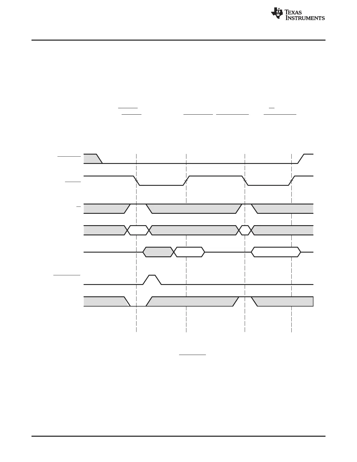
21.2.6.7 Performing a Multiplexed Access
Figure 21-2 shows an example of signal connections for multiplexed transfers. Figure 21-4 and Figure 21-
5 show typical HPI signal activity when performing a read and write transfer, respectively. In these cases,
the falling edge of internal HSTRB is used to latch the UHPI_HCNTL[1:0], UHPI_HR/W, and UHPI_HHWIL
states into the HPI. Internal HSTRB is derived from UHPI_HCS, UHPI_HDS1, and UHPI_HDS2 as
described in Section 21.2.6.4.
Figure 21-4. Multiplexed-Mode Host Read Cycle
NOTE: Depending on the type of write operation (HPID without autoincrementing, HPIA, HPIC, or HPID with
autoincrementing) and the state of the FIFO, transitions on UHPI_HRDY may or may not occur. For more information,
see Section 21.2.6.9.