CEVT1 CEVT2 CEVT1
FFFFFFFF
CTR[0−31]
00000000
CAPx pin
t
MOD4
CTR
CAP1
CAP2
CAP3
CAP4
Capture registers [1−4]
CEVT3 CEVT4
0 1 2 3 0 1
XX
XX
t
2
XX
t
3
XX
t
4
T
1
T
2
T
3
T
4
CTR value at CEVT1
t
1
All capture values valid
(can be read) at this time
Polarity selection
www.ti.com
Applications
259
SPRUH91D–March 2013–Revised September 2016
Submit Documentation Feedback
Copyright © 2013–2016, Texas Instruments Incorporated
Enhanced Capture (eCAP) Module
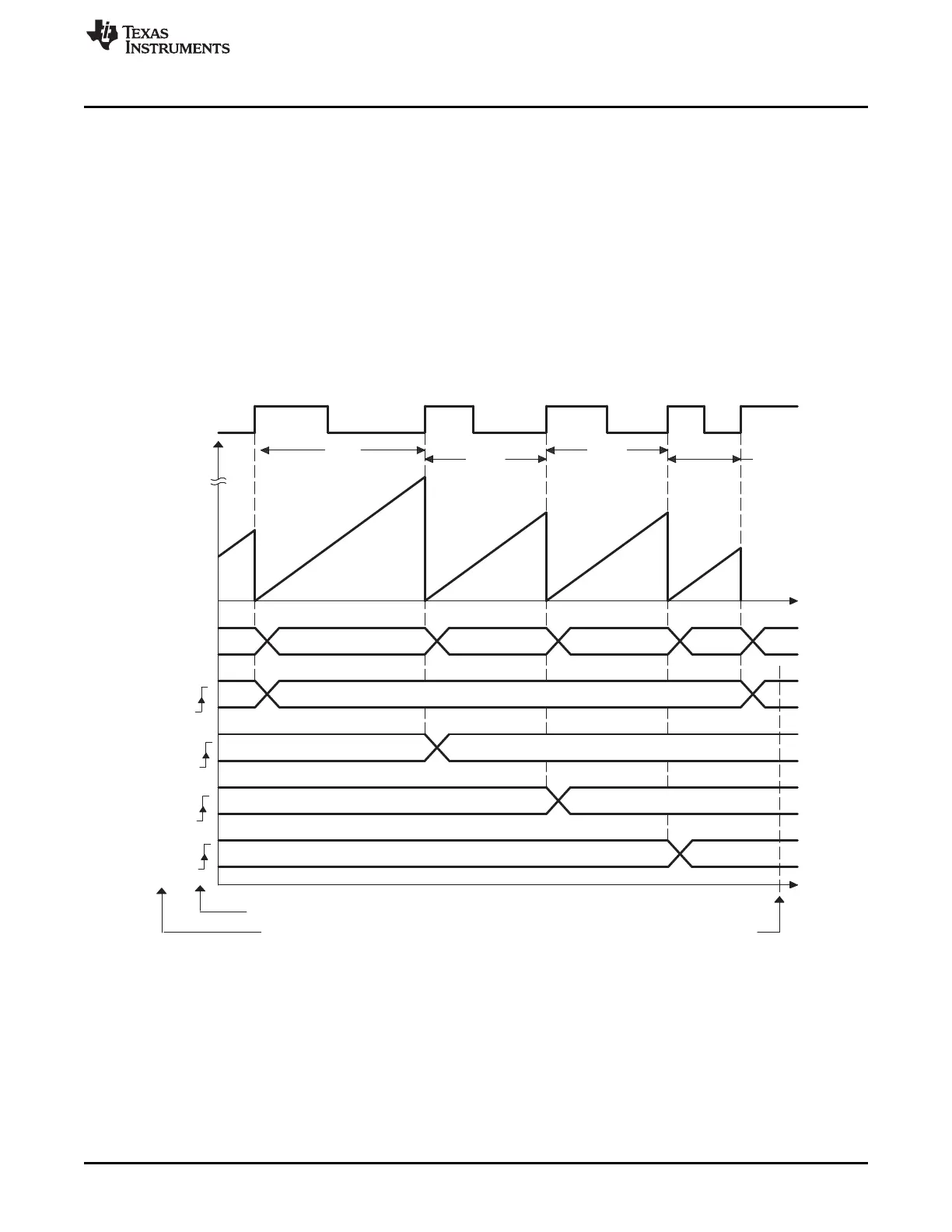
13.3.3 Time Difference (Delta) Operation Rising Edge Trigger Example
Figure 13-12 shows how the eCAP module can be used to collect Delta timing data from pulse train
waveforms. Here Continuous Capture mode (TSCTR counts-up without resetting, and Mod4 counter
wraps around) is used. In Delta-time mode, TSCTR is Reset back to Zero on every valid event. Here
Capture events are qualified as Rising edge only. On an event, TSCTR contents (time-stamp) is captured
first, and then TSCTR is reset to Zero. The Mod4 counter then increments to the next state. If TSCTR
reaches FFFF FFFFh (maximum value), before the next event, it wraps around to 0000 0000h and
continues, a CNTOVF (counter overflow) Flag is set, and an Interrupt (if enabled) occurs. The advantage
of Delta-time Mode is that the CAPn contents directly give timing data without the need for CPU
calculations: Period1 = T
1
, Period2 = T
2
,…etc. As shown in Figure 13-12, the CEVT1 event is a good
trigger point to read the timing data, T
1
, T
2
, T
3
, T
4
are all valid here.
Figure 13-12. Capture Sequence for Delta Mode Time-Stamp, Rising Edge Detect