Readdata
Write
command
Writedata
DestinationFIFO
registerset
Data
FIFO
Transferrequest
submission
EDMA3TCn
EDMA3TC_ERRINT
Tocompletion
detectionlogic
inEDMA3CC
Read
command
Sourceactive
registerset
Read
controller
Write
controller
Program
registerset
www.ti.com
Architecture
443
SPRUH91D–March 2013–Revised September 2016
Submit Documentation Feedback
Copyright © 2013–2016, Texas Instruments Incorporated
Enhanced Direct Memory Access (EDMA3) Controller
16.2.1.2 EDMA3 Transfer Controller (EDMA3TC)
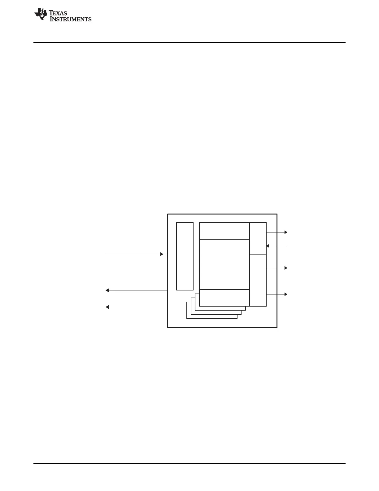
Figure 16-3 shows a functional block diagram of the EDMA3 transfer controller (EDMA3TC).
The main blocks of the EDMA3TC are:
• DMA program register set: The DMA program register set stores the transfer requests received from
the EDMA3 channel controller (EDMA3CC).
• DMA source active register set: The DMA source active register set stores the context for the DMA
transfer request currently in progress in the read controller.
• Read controller: The read controller issues read commands to the source address.
• Destination FIFO register set: The destination (Dst) FIFO register set stores the context for the DMA
transfer request(s) currently in progress or pending in the write controller.
• Write controller: The write controller issues write commands/write data to the destination address.
• Data FIFO: The data FIFO holds temporary in-flight data. The source peripheral's read data is stored in
the data FIFO and subsequently written to the destination peripheral/end point by the write controller.
• Completion interface: The completion interface sends completion codes to the EDMA3CC when a
transfer completes, and is used for generating interrupts and chained events (see Section 16.2.5 for
details on transfer completion reporting).
Figure 16-3. EDMA3 Transfer Controller (EDMA3TC) Block Diagram
When the EDMA3TC is idle and receives its first TR, the TR is received in the DMA program register set,
where it transitions to the DMA source active set and the destination FIFO register set immediately. The
source active register set tracks the commands for the source side of the transfers, and the destination
FIFO register set tracks commands for the destination side of the transfer. The second TR (if pending from
EDMA3CC) is loaded into the DMA program set, ensuring it can start as soon as possible when the active
transfer (the transfer in the source active set) is completed. As soon as the current active set is
exhausted, the TR is loaded from the DMA program register set into the DMA source active register set as
well as to the appropriate entry in the destination FIFO register set.
The read controller issues read commands governed by the rules of command fragmentation and
optimization. These are issued only when the data FIFO has space available for the read data. The
number of read commands issued depends on the TR transfer size. The TC write controller starts issuing
write commands as soon as sufficient data is read in the data FIFO for the write controller to issue
optimally sized write commands following the rules for command fragmentation and optimization. For
details on command fragmentation and optimization, see Section 16.2.11.1.2.