t
RC
(m)
Strobe
Setup Hold
EMA_CS[n]
EMA_A[x:0]
EMA_BA[1:0]
EMA_OE
EMA_D[x:0]
t
ACC
(m)
t
SU
t
H
t
COD
(m)
t
OH
(m)
Example Configuration
www.ti.com
742
SPRUH91D–March 2013–Revised September 2016
Submit Documentation Feedback
Copyright © 2013–2016, Texas Instruments Incorporated
External Memory Interface A (EMIFA)
The EMIFA offers an additional parameter, TA, that defines the turnaround time between read and write
cycles. This parameter protects against the situation when the output turn-off time of the memory is longer
than the time it takes to start the next write cycle. If this is the case, the EMIFA will drive data at the same
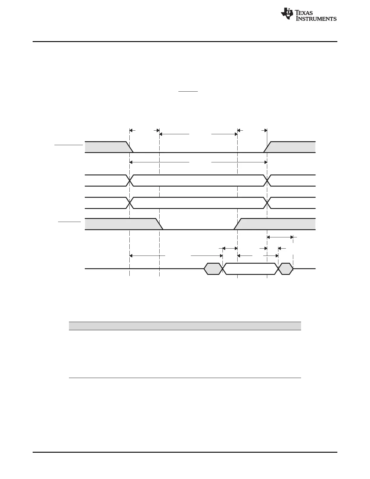
time as the memory, causing contention on the bus. By examining Figure 18-23, the equation for TA can
be derived as:
Figure 18-23. Timing Waveform of an ASRAM Read
For a write access, Table 18-34 lists the AC timing specifications that must be satisfied.
Table 18-34. ASRAM Input Timing Requirements for a Write
Parameter Description
t
WP
Write Pulse width
t
AW
Address valid to end of Write
t
DS
Data Setup time
t
WR
Write Recovery time
t
DH
Data Hold time
t
WC
Write Cycle time















 To Next Page