IPC=0
Datapinssamples
bythedisplay
Datapins
change
LCD_PCLK
LCD_D[x:0]
LCD_HSYNC
LCD_VSYNC
2and2/3pixel 2and2/3pixel 2and2/3pixel 2and2/3pixel
Pixel0
through3
Pixel4
through7
Pixel8
through11
Pixel12
through15
IPC=0
MONO8B=0
Datapinssamples
bythedisplay
Datapins
change
LCD_PCLK
LCD_D[x:0]
LCD_HSYNC
LCD_VSYNC
www.ti.com
Registers
963
SPRUH91D–March 2013–Revised September 2016
Submit Documentation Feedback
Copyright © 2013–2016, Texas Instruments Incorporated
Liquid Crystal Display Controller (LCDC)
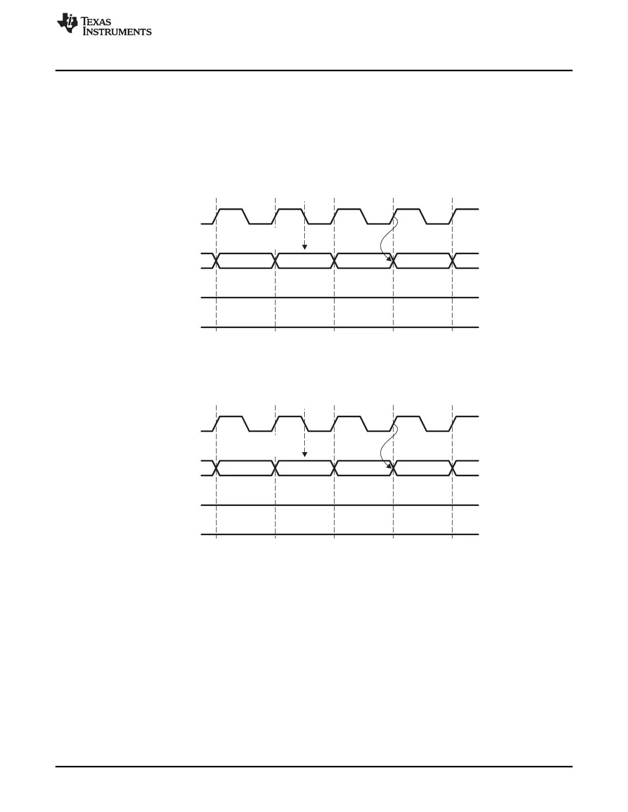
23.3.8.3 TFT_STN (TFT_STN)
The TFT_STN (TFT_STN) bit selects whether the LCD controller operates in passive (STN) or active
(TFT) display control mode. When TFT_STN = 0, passive or STN mode is selected. LCD data flows from
the frame buffer memory, via the LCD dedicated DMA channel, to the palette (the palette is bypassed for
the 12 and 16 BPP modes), to the dithering logic and the output FIFO before being output on the LCD
data pins. The clock and data pin behaviors is shown for the monochrome passive mode (Figure 23-23)
and for the color passive mode (Figure 23-24).
Figure 23-23. Monochrome Passive Mode Pixel Clock and Data Pin Timing
Figure 23-24. Color Passive Mode Pixel Clock and Data Pin Timing