Example Configuration
www.ti.com
808
SPRUH91D–March 2013–Revised September 2016
Submit Documentation Feedback
Copyright © 2013–2016, Texas Instruments Incorporated
External Memory Interface B (EMIFB)
Configuring SDRAM Timing Registers (SDTIM1 and SDTIM2)
The SDRAM timing register 1 (SDTIM1) and SDRAM timing register 2 (SDTIM2) configure the EMIFB
memory controller to meet the data sheet timing parameters of the attached SDRAM device. Each field in
SDTIM1 and SDTIM2 corresponds to a timing parameter in the SDRAM data sheet specification.
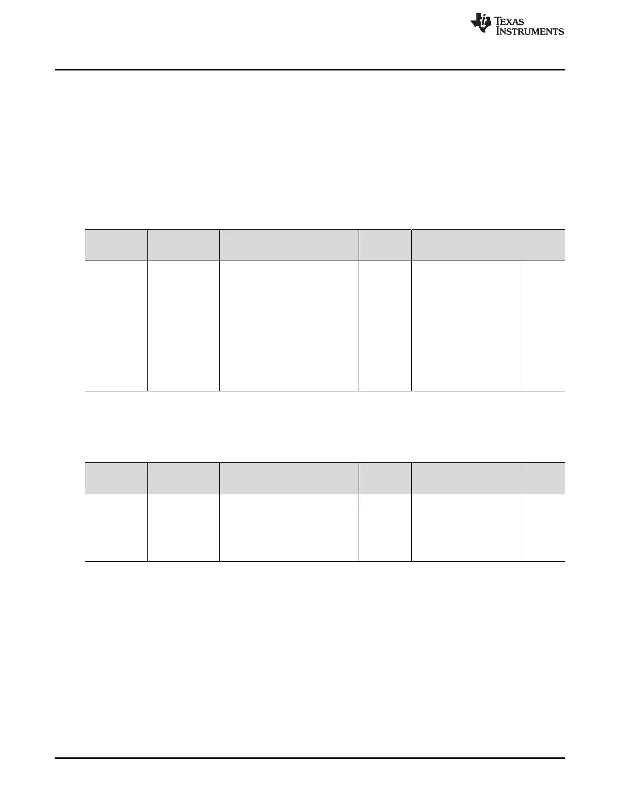
Table 19-21 and Table 19-22 display the register field name and corresponding SDRAM data sheet
parameter name along with the data sheet value. These tables also provide a formula to calculate the
register field value and displays the resulting calculation. Each of the equations include a minus 1 because
the register fields are defined in terms of SDRAM clock cycles minus 1. See Section 19.4.3 and
Section 19.4.4 for more information.
Table 19-21. SDTIM1 Configuration
Register Field
Name
SDRAM Data
Manual
Parameter Name Description
Data
Manual
Value (ns)
Formula
(Register field must be ≥)
Register
Value
T_RFC t
RFC
refresh cycle time 66 (t
RFC
× f
EMB_CLK
) - 1 8
T_RP t
RP
precharge command to refresh or
activate command
20 (t
RP
× f
EMB_CLK
) - 1 2
T_RCD t
RCD
activate command to read/write
command
20 (t
RCD
× f
EMB_CLK
) - 1 2
T_WR t
WR
write recovery time 15 (t
WR
× f
EMB_CLK
) - 1 1
T_RAS t
RAS
active to precharge command 44 (t
RAS
× f
EMB_CLK
) - 1 5
T_RC t
RC
activate to activate command in the
same bank
66 (t
RC
× f
EMB_CLK
) - 1 8
T_RRD t
RRD
activate to activate command in a
different bank
15 (t
RRD
× f
EMB_CLK
) - 1 1
(1)
Register field value must be ≤ the calculated value
(2)
Register field value must be ≥ the calculated value
Table 19-22. SDTIM2 Configuration
Register Field
Name
SDRAM Data
Manual
Parameter Name Description
Data
Manual
Value (ns) Formula
Register
Value
T_RAS_MAX t
RAS_MAX
refresh cycle time 100K (t
RAS_MAX
/ SDRAM refresh
rate) - 1
(1)
13
T_XSR t
XSR
self refresh exit to any command
other than a read command
75 (t
XSR
× f
EMB_CLK
) - 1
(2)
9
T_CKE t
CKE
number of clock cycles between
EMB_CKE changes
38 (t
CKE
× f
EMB_CLK
) - 1
(2)
5

 Loading...


