www.ti.com
Registers
823
SPRUH91D–March 2013–Revised September 2016
Submit Documentation Feedback
Copyright © 2013–2016, Texas Instruments Incorporated
External Memory Interface B (EMIFB)
19.4.12 Interrupt Mask Set Register (IMSR)
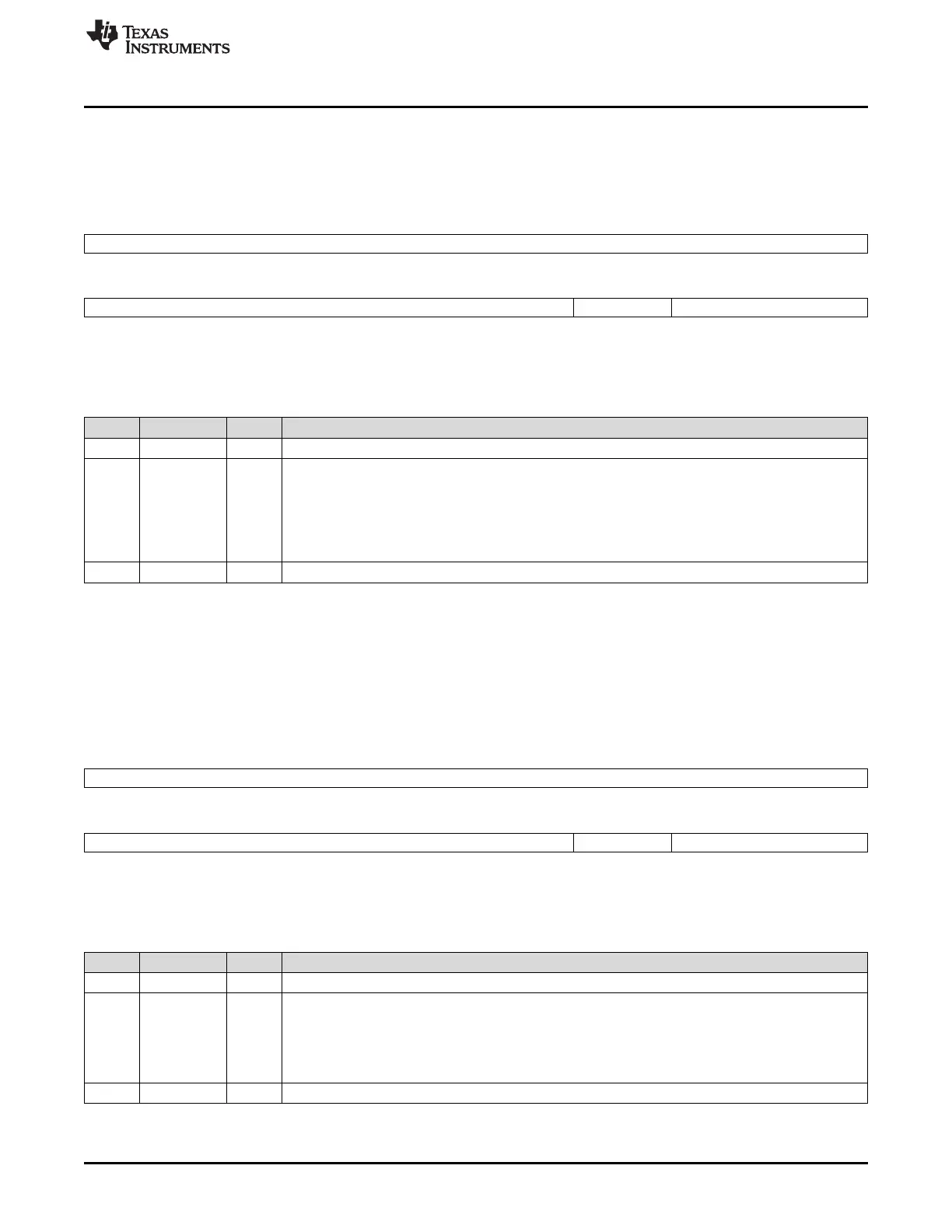
The interrupt mask set register (IMSR) enables the memory controller interrupt. The IMSR is shown in
Figure 19-27 and described in Table 19-39.
Figure 19-27. Interrupt Mask Set Register (IMSR)
31 8
Reserved
R-0
7 3 2 1 0
Reserved LTMSET Reserved
R-0 R/W-0 R-0
LEGEND: R/W = Read/Write; R = Read only; -n = value after reset
Table 19-39. Interrupt Mask Set Register (IMSR) Field Descriptions
Bit Field Value Description
31-3 Reserved 0 All writes to these bit(s) must always have a value of 0.
2 LTMSET Mask set for LTM bit in the interrupt mask register (IMR). Writing a 1 will enable the interrupt, and set
this bit as well as the LTMCLR bit in the interrupt mask clear register (IMCR). The interrupt will not be
enabled, and this bit as well as the LTMCLR bit will not be set if a 1 is written to this bit and the
LTMCLR bit at the same time. Writing a 0 has no effect.
0 Line trap interrupt is not enabled; a write of 1 to the LTMCLR bit in IMCR occurred.
1 Line trap interrupt is enabled.
1-0 Reserved 0 All writes to these bit(s) must always have a value of 0.
19.4.13 Interrupt Mask Clear Register (IMCR)
The interrupt mask clear register (IMCR) disables the memory controller interrupt. Once an interrupt is
enabled, it may be disabled by writing a 1 to the IMCR bit. The IMCR is shown in Figure 19-28 and
described in Table 19-40.
Figure 19-28. Interrupt Mask Clear Register (IMCR)
31 8
Reserved
R-0
7 3 2 1 0
Reserved LTMCLR Reserved
R-0 R/W-0 R-0
LEGEND: R/W = Read/Write; R = Read only; -n = value after reset
Table 19-40. Interrupt Mask Clear Register (IMCR) Field Descriptions
Bit Field Value Description
31-3 Reserved 0 All writes to these bit(s) must always have a value of 0.
2 LTMCLR Mask clear for LTM bit in the interrupt mask register (IMR). Writing a 1 will disable the interrupt, and
clear this bit as well as the LTMSET bit in the interrupt mask set register (IMSR). Writing a 0 has no
effect.
0 Line trap interrupt is not enabled.
1 Line trap interrupt is enabled; a write of 1 to the LTMSET bit in IMSR occurred.
1-0 Reserved 0 All writes to these bit(s) must always have a value of 0.















 To Next Page