Registers
www.ti.com
822
SPRUH91D–March 2013–Revised September 2016
Submit Documentation Feedback
Copyright © 2013–2016, Texas Instruments Incorporated
External Memory Interface B (EMIFB)
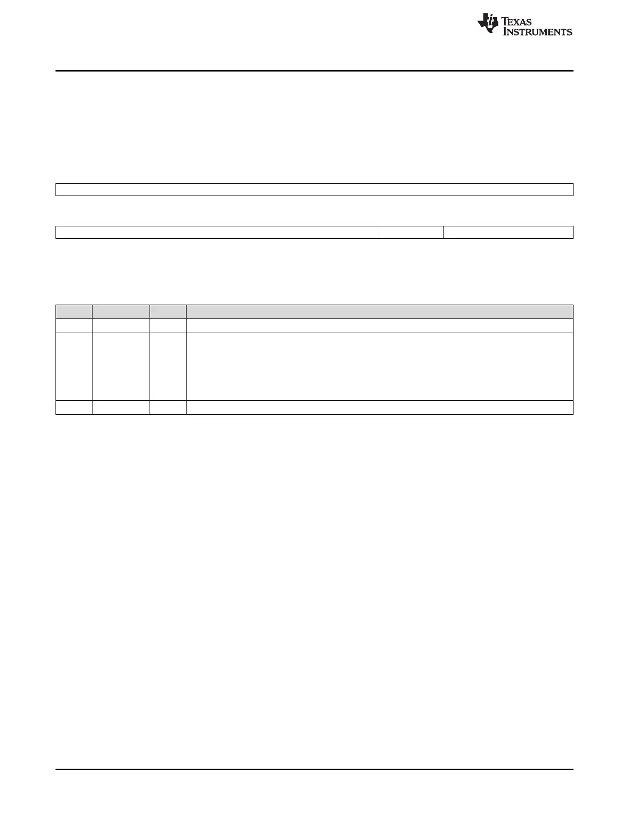
19.4.11 Interrupt Mask Register (IMR)
The interrupt mask register (IMR) displays the status of the interrupt when it is enabled. If the interrupt
condition occurs and the corresponding bit in the interrupt mask set register (IMSR) is set, then the IMR
bit is set. The IMR bit is not set if the interrupt is not enabled in IMSR. The IMR is shown in Figure 19-26
and described in Table 19-38.
Figure 19-26. Interrupt Mask Register (IMR)
31 8
Reserved
R-0
7 3 2 1 0
Reserved LTM Reserved
R-0 R/W-0 R-0
LEGEND: R/W = Read/Write; R = Read only; -n = value after reset
Table 19-38. Interrupt Mask Register (IMR) Field Descriptions
Bit Field Value Description
31-3 Reserved 0 All writes to these bit(s) must always have a value of 0.
2 LTM Masked Line Trap. Set to 1 by hardware to indicate illegal memory access type, only if the LTMSET bit
in the interrupt mask set register (IMSR) is set to 1. Writing a 1 will clear this bit as well as the LT bit in
the interrupt raw register (IRR). Writing a 0 has no effect.
0 Line trap has not occurred.
1 Line trap occurred due to use of unsupported addressing mode (only set if the LTMSET bit in IMSR is
set).
1-0 Reserved 0 All writes to these bit(s) must always have a value of 0.

 Loading...


