CTR=0
CTR=CMPB
X
En
SyncOut
Phase reg
Ext SyncIn
(optional)
EPWM1A
EPWM1B
SyncOut
Phase reg
CTR=CMPB
CTR=0
X
En
EPWM2B
EPWM2A
Slave
Master
SyncIn
SyncIn
1
2
Φ=0°
Φ=120°
Applications to Power Topologies
www.ti.com
362
SPRUH91D–March 2013–Revised September 2016
Submit Documentation Feedback
Copyright © 2013–2016, Texas Instruments Incorporated
Enhanced High-Resolution Pulse-Width Modulator (eHRPWM)
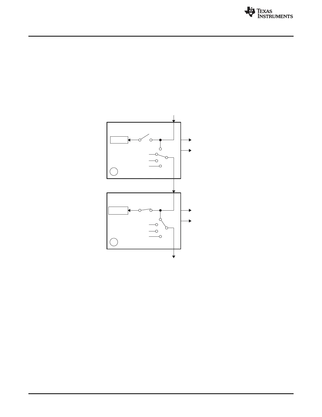
14.3.7 Practical Applications Using Phase Control Between PWM Modules
So far, none of the examples have made use of the phase register (TBPHS). It has either been set to zero
or its value has been a don't care. However, by programming appropriate values into TBPHS, multiple
PWM modules can address another class of power topologies that rely on phase relationship between
legs (or stages) for correct operation. As described in the TB module section, a PWM module can be
configured to allow a SyncIn pulse to cause the TBPHS register to be loaded into the TBCNT register. To
illustrate this concept, Figure 14-59 shows a master and slave module with a phase relationship of 120°,
that is, the slave leads the master.
Figure 14-59. Configuring Two PWM Modules for Phase Control
Figure 14-60 shows the associated timing waveforms for this configuration. Here, TBPRD = 600 for both
master and slave. For the slave, TBPHS = 200 (200/600 × 360° = 120°). Whenever the master generates
a SyncIn pulse (CTR = PRD), the value of TBPHS = 200 is loaded into the slave TBCNT register so the
slave time-base is always leading the master's time-base by 120°.