7 6 5 4 3 7 6 345
7 6 5 4 3 7 6 345
Master SPI
Int. flag
Slave SPI
Int. flag
SPIx_SOMI
from slave
SPI SIMOx_
from master
Clock polarity = 1
Clock phase = 1
SPI SCS[n]x_
SPI CLK signal options:x_
K
B
SPI ENAx_
Clock polarity = 1
Clock phase = 0
Clock polarity = 0
Clock phase = 1
Clock polarity = 0
Clock phase = 0
www.ti.com
Architecture
1189
SPRUH91D–March 2013–Revised September 2016
Submit Documentation Feedback
Copyright © 2013–2016, Texas Instruments Incorporated
Serial Peripheral Interface (SPI)
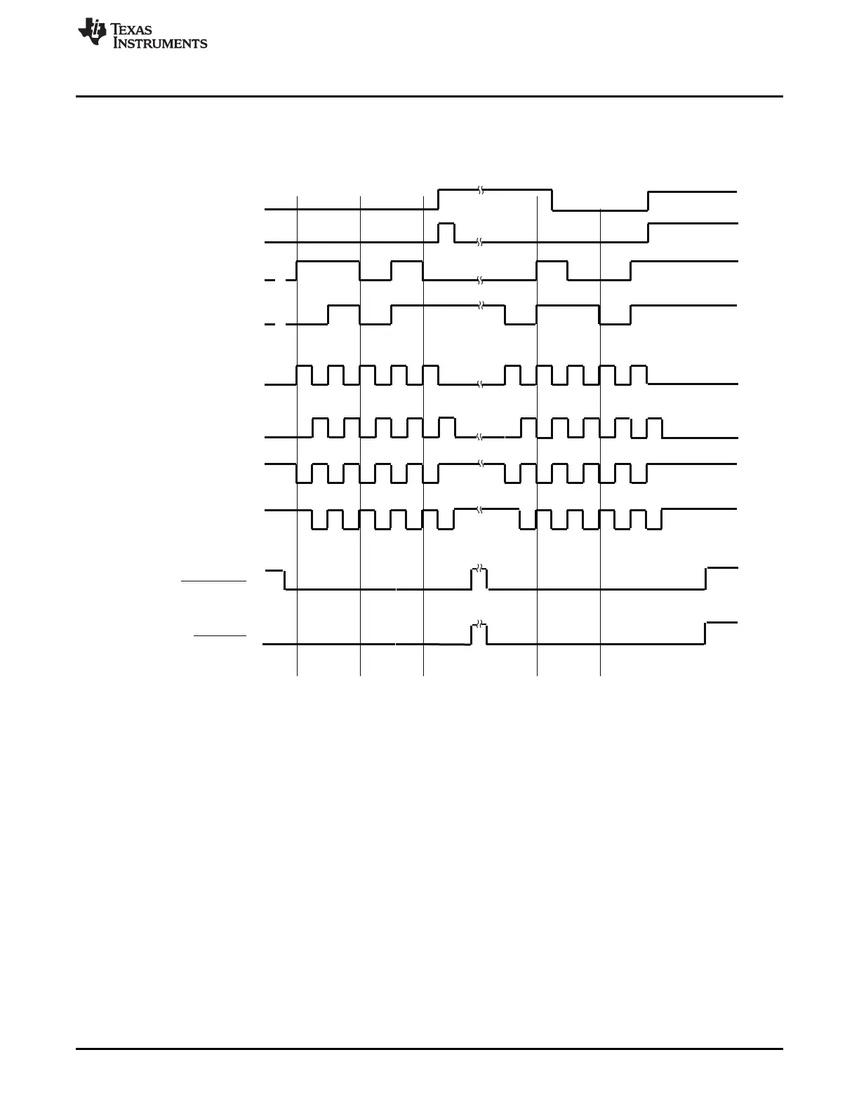
27.2.11.4 SPI Data Transfer Example
Figure 27-12 illustrates an SPI data transfer between two devices using a character length of five bits.
Figure 27-12. Five Bits per Character (5-Pin Option)
27.2.12 Interrupt Support
The SPI interrupt system is controlled by three registers:
• The SPI interrupt level register (SPILVL) controls the interrrupt level. The interrupt level must be set to
select the level one interrupt (INT1).
• The SPI interrupt register (SPIINT) contains bits to selectively enable/disable each interrupt event.
• The SPI flag register (SPIFLG) contains flags indicating the interrupt conditions that have occurred.
To identify the interrupt source in the SPI peripheral, the CPU reads the SPI flag status register (SPIFLG)
or the INTVECT1 code in the SPI interrupt vector register 1 (INTVEC1).
Check your device-specific data manual for details on the exact CPU interrupt numbers assigned to the
SPI interrupts.















 To Next Page