www.ti.com
Registers
761
SPRUH91D–March 2013–Revised September 2016
Submit Documentation Feedback
Copyright © 2013–2016, Texas Instruments Incorporated
External Memory Interface A (EMIFA)
18.4.3 SDRAM Configuration Register (SDCR)
The SDRAM configuration register (SDCR) is used to configure various parameters of the SDRAM
controller such as the number of internal banks, the internal page size, and the CAS latency to match
those of the attached SDRAM device. In addition, this register is used to put the attached SDRAM device
into Self-Refresh mode. The SDCR is shown in Figure 18-33 and described in Table 18-51.
NOTE: Writing to the lower three bytes of this register will cause the EMIFA to start the SDRAM
initialization sequence described in Section 18.2.4.4.
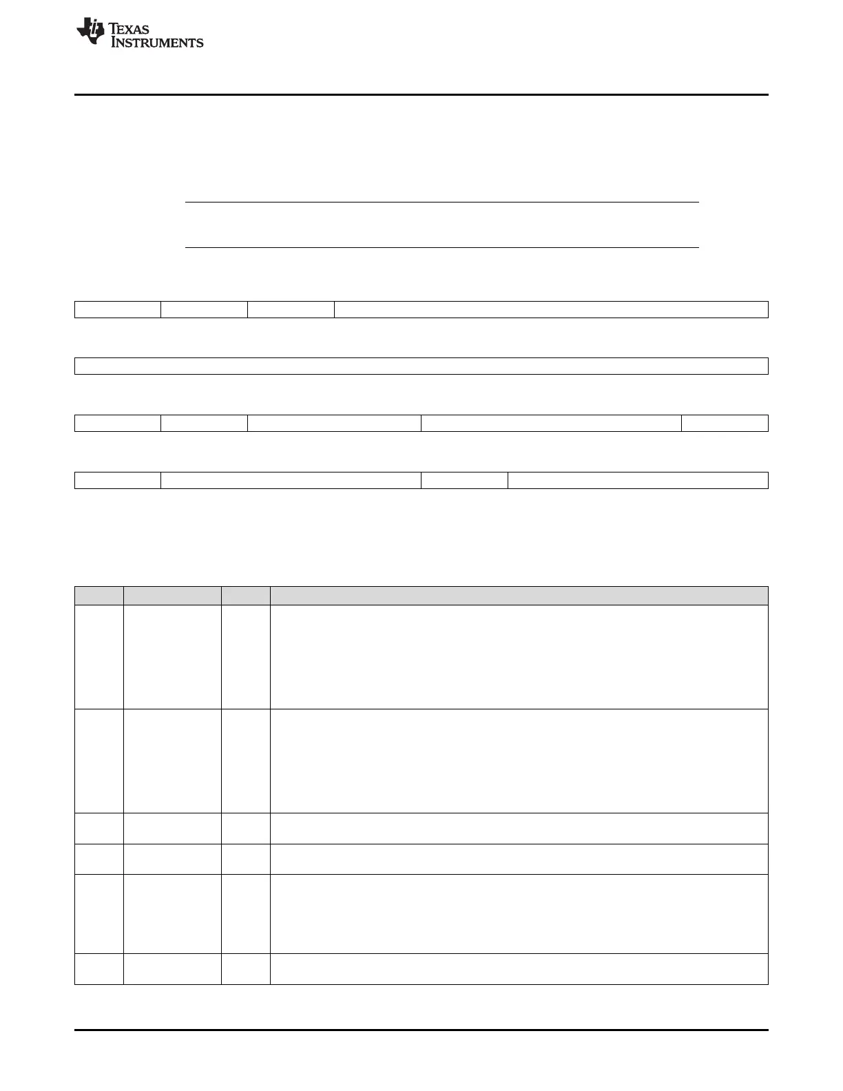
Figure 18-33. SDRAM Configuration Register (SDCR)
31 30 29 28 24
SR PD PDWR Reserved
R/W-0 R/W-0 R/W-0 R-0
23 16
Reserved
R-0
15 14 13 12 11 9 8
Reserved NM
(A)
Reserved CL BIT11_9LOCK
R-0 R/W-0 R-0 R/W-3h R/W-0
7 6 4 3 2 0
Reserved IBANK Reserved PAGESIZE
R-0 R/W-2h R-0 R/W-0
LEGEND: R/W = Read/Write; R = Read only; -n = value after reset
A. The NM bit must be set to 1 if the EMIFA on your device only has 16 data bus pins.
Table 18-51. SDRAM Configuration Register (SDCR) Field Descriptions
Bit Field Value Description
31 SR Self-Refresh mode bit. This bit controls entering and exiting of the Self-Refresh mode described in
Section 18.2.4.7. The field should be written using a byte-write to the upper byte of SDCR to avoid
triggering the SDRAM initialization sequence.
0 Writing a 0 to this bit will cause connected SDRAM devices and the EMIFA to exit the Self-Refresh
mode.
1 Writing a 1 to this bit will cause connected SDRAM devices and the EMIFA to enter the Self-
Refresh mode.
30 PD Power Down bit. This bit controls entering and exiting of the power-down mode. The field should be
written using a byte-write to the upper byte of SDCR to avoid triggering the SDRAM initialization
sequence. If both SR and PD bits are set, the EMIFA will go into Self Refresh.
0 Writing a 0 to this bit will cause connected SDRAM devices and the EMIFA to exit the power-down
mode.
1 Writing a 1 to this bit will cause connected SDRAM devices and the EMIFA to enter the power-
down mode.
29 PDWR Perform refreshes during power down. Writing a 1 to this bit will cause EMIFA to exit power-down
state and issue and AUTO REFRESH command every time Refresh May level is set.
28-15 Reserved 0 Reserved. The reserved bit location is always read as 0. If writing to this field, always write the
default value of 0.
14 NM Narrow mode bit. This bit defines whether a 16- or 32-bit-wide SDRAM is connected to the EMIFA.
This bit field must always be set to 1. Writing to this field triggers the SDRAM initialization
sequence.
0 32-bit SDRAM data bus is used.
1 16-bit SDRAM data bus is used.
13-12 Reserved 0 Reserved. The reserved bit location is always read as 0. If writing to this field, always write the
default value of 0.

 Loading...


