Time interval
1 0 1 1 0 0 1 0 1 1 0
1 0 1 1 0 1 10 0 0 11 0 1 0 0 1 0 1 0 11
Cell
Clock
128 x Fs
Data
(unencoded)
Biphase
mark signal
(at pin AXR[n])
Internal
to McASP
At pin
www.ti.com
989
SPRUH91D–March 2013–Revised September 2016
Submit Documentation Feedback
Copyright © 2013–2016, Texas Instruments Incorporated
Multichannel Audio Serial Port (McASP)
24.0.18.2 S/PDIF Coding Format
The McASP transmitter supports the S/PDIF format with 3.3V biphase-mark encoded output. The S/PDIF
format is supported by the digital audio interface transmit (DIT) transfer mode of the McASP. This section
briefly discusses the S/PDIF coding format.
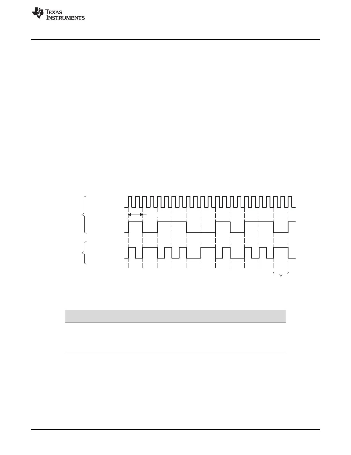
24.0.18.2.1 Biphase-Mark Code (BMC)
In S/PDIF format, the digital signal is coded using the biphase-mark code (BMC). The clock, frame, and
data are embedded in only one signal—the data pin AXR[n]. In the BMC system, each data bit is encoded
into two logical states (00, 01, 10, or 11) at the pin. These two logical states form a cell. The duration of
the cell, which equals to the duration of the data bit, is called a time interval. A logical 1 is represented by
two transitions of the signal within a time interval, which corresponds to a cell with logical states 01 or 10.
A logical 0 is represented by one transition within a time interval, which corresponds to a cell with logical
states 00 or 11. In addition, the logical level at the start of a cell is inverted from the level at the end of the
previous cell. Figure 24-9 and Table 24-1 show how data is encoded to the BMC format.
As shown in Figure 24-9, the frequency of the clock is twice the unencoded data bit rate. In addition, the
clock is always programmed to 128 × f
s
, where f
s
is the sample rate (see Section 24.0.18.2.3 for details on
how this clock rate is derived based on the S/PDIF format). The device receiving in S/PDIF format can
recover the clock and frame information from the BMC signal.
Figure 24-9. Biphase-Mark Code (BMC)
Table 24-1. Biphase-Mark Encoder
Data (Unencoded)
Previous State at Pin
AXR[n] BMC-Encoded Cell Output at AXR[n]
0 0 11
0 1 00
1 0 10
1 1 01

 Loading...


