Φ=0°
CTR=0
CTR=CMPB
X
En
SyncOut
Phase reg
Ext SyncIn
(optional)
EPWM1A
EPWM1B
SyncOut
Phase reg
CTR=CMPB
CTR=0
X
En
EPWM2B
EPWM2A
Slave
Master
EPWM1A
EPWM1B
EPWM2A
EPWM2B EPWM3B
EPWM3A
VAB
VCD
VEF
3 phase motor
EPWM4B EPWM5B
VAB
EPWM4A
VCD
EPWM5A
EPWM6B
3 phase motor
VEF
EPWM6A
3 phase inverter #1
3 phase inverter #2
1
2
CTR=0
CTR=CMPB
Phase reg
3
Slave
SyncOut
X
En
EPWM3B
EPWM3A
Phase reg
CTR=CMPB
CTR=0
4
Slave
SyncOut
X
EPWM4A
EPWM4B
En
SyncOut
CTR=0
CTR=CMPB
Phase reg
Phase reg
CTR=CMPB
CTR=0
Slave
6
5
Slave
X
En
SyncIn
EPWM6B
EPWM6A
SyncOut
X
EPWM5A
EPWM5B
En
Φ=0°
Φ=0°
Φ=0°
Φ=0°
Φ=0°
SyncIn
SyncIn
SyncIn
SyncIn
SyncIn
Applications to Power Topologies
www.ti.com
358
SPRUH91D–March 2013–Revised September 2016
Submit Documentation Feedback
Copyright © 2013–2016, Texas Instruments Incorporated
Enhanced High-Resolution Pulse-Width Modulator (eHRPWM)
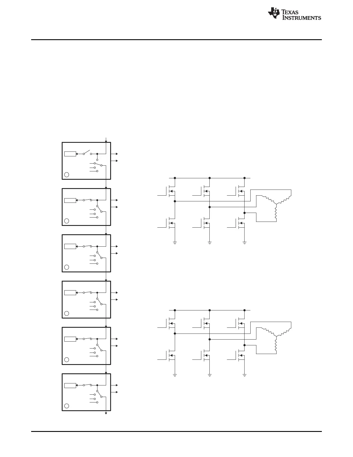
14.3.6 Controlling Dual 3-Phase Inverters for Motors (ACI and PMSM)
The idea of multiple modules controlling a single power stage can be extended to the 3-phase Inverter
case. In such a case, six switching elements can be controlled using three PWM modules, one for each
leg of the inverter. Each leg must switch at the same frequency and all legs must be synchronized. A
master + two slaves configuration can easily address this requirement. Figure 14-57 shows how six PWM
modules can control two independent 3-phase Inverters; each running a motor.
As in the cases shown in the previous sections, we have a choice of running each inverter at a different
frequency (module 1 and module 4 are masters as in Figure 14-57), or both inverters can be synchronized
by using one master (module 1) and five slaves. In this case, the frequency of modules 4, 5, and 6 (all
equal) can be integer multiples of the frequency for modules 1, 2, 3 (also all equal).
Figure 14-57. Control of Dual 3-Phase Inverter Stages as Is Commonly Used in Motor Control

 Loading...


