EPWMxINT
EPWMxTZINT
EPWMxSYNCI
EPWMxSYNCO
Time-base (TB) module
Counter-compare (CC) module
Action-qualifier (AQ) module
Dead-band (DB) module
PWM-chopper (PC) module
Event-trigger (ET) module
Trip-zone (TZ) module
Peripheral bus
ePWM module
TZ1 to TZn
EPWMxA
EPWMxB
Interrupt
controller
GPIO
MUX
www.ti.com
Introduction
285
SPRUH91D–March 2013–Revised September 2016
Submit Documentation Feedback
Copyright © 2013–2016, Texas Instruments Incorporated
Enhanced High-Resolution Pulse-Width Modulator (eHRPWM)
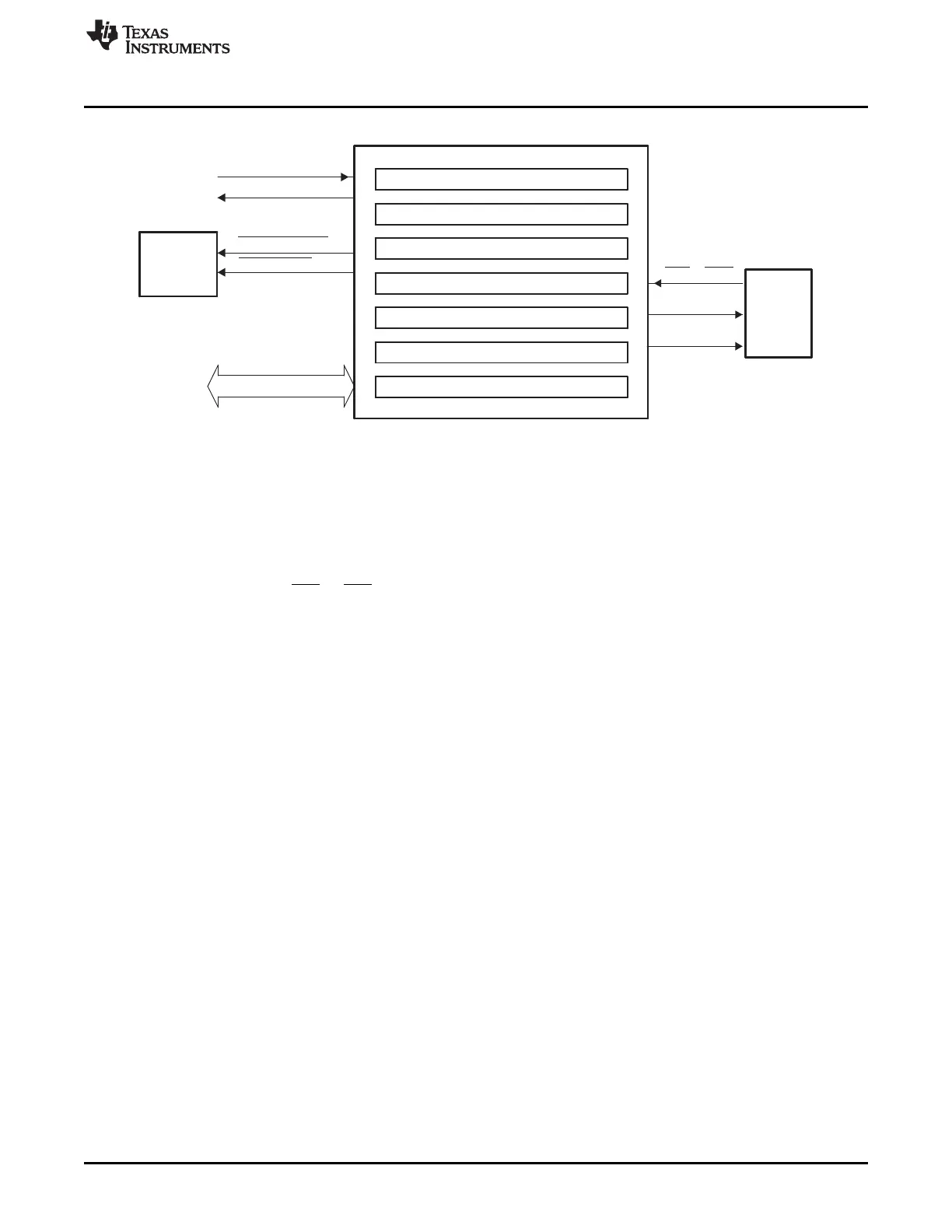
Figure 14-2. Submodules and Signal Connections for an ePWM Module
Figure 14-3 shows more internal details of a single ePWM module. The main signals used by the ePWM
module are:
• PWM output signals (EPWMxA and EPWMxB). The PWM output signals are made available
external to the device through the GPIO peripheral described in the system control and interrupts guide
for your device.
• Trip-zone signals (TZ1 to TZn). These input signals alert the ePWM module of an external fault
condition. Each module on a device can be configured to either use or ignore any of the trip-zone
signals. The trip-zone signal can be configured as an asynchronous input through the GPIO peripheral.
See your device-specific data manual to determine how many trip-zone pins are available in the
device.
• Time-base synchronization input (EPWMxSYNCI) and output (EPWMxSYNCO) signals. The
synchronization signals daisy chain the ePWM modules together. Each module can be configured to
either use or ignore its synchronization input. The clock synchronization input and output signal are
brought out to pins only for ePWM1 (ePWM module #1). The synchronization output for ePWM1
(EPWM1SYNCO) is also connected to the SYNCI of the first enhanced capture module (eCAP1).
• Peripheral Bus. The peripheral bus is 32-bits wide and allows both 16-bit and 32-bit writes to the
ePWM register file.
Figure 14-3 also shows the key internal submodule interconnect signals. Each submodule is described in
detail in Section 14.2.