TBCTL[SYNCOSEL]
TBPRD
Period Active
TBPRD
Period Shadow
16
TBCTL[SWFSYNC]
CTR = PRD
TBPHS
Phase Active Reg
Counter
UP/DOWN
16
Sync
Out
Select
EPWMxSYNCO
Reset
Load
16
TBCTL[PHSEN]
CTR = 0
CTR = CMPB
Disable
X
EPWMxSYNCI
TBCTL[PRDLD]
TBCNT
Mode
TBCTL[CTRMODE]
CTR = 0
CTR_max
TBCLK
Clock
Prescale
SYSCLKOUT
TBCLK
TBCTL[HSPCLKDIV]
TBCTL[CLKDIV]
CTR_dir
TBCNT
Counter Active Reg
clk
Max
Dir
Zero
www.ti.com
Architecture
293
SPRUH91D–March 2013–Revised September 2016
Submit Documentation Feedback
Copyright © 2013–2016, Texas Instruments Incorporated
Enhanced High-Resolution Pulse-Width Modulator (eHRPWM)
14.2.3.2 Controlling and Monitoring the Time-Base Submodule
Table 14-3 lists the registers used to control and monitor the time-base submodule.
(1)
This register is available only on ePWM instances that include the high-resolution extension (HRPWM). On ePWM modules that
do not include the HRPWM, this location is reserved. See your device-specific data manual to determine which ePWM instances
include this feature.
Table 14-3. Time-Base Submodule Registers
Acronym Register Description Address Offset Shadowed
TBCTL Time-Base Control Register 0h No
TBSTS Time-Base Status Register 2h No
TBPHSHR HRPWM extension Phase Register
(1)
4h No
TBPHS Time-Base Phase Register 6h No
TBCNT Time-Base Counter Register 8h No
TBPRD Time-Base Period Register Ah Yes
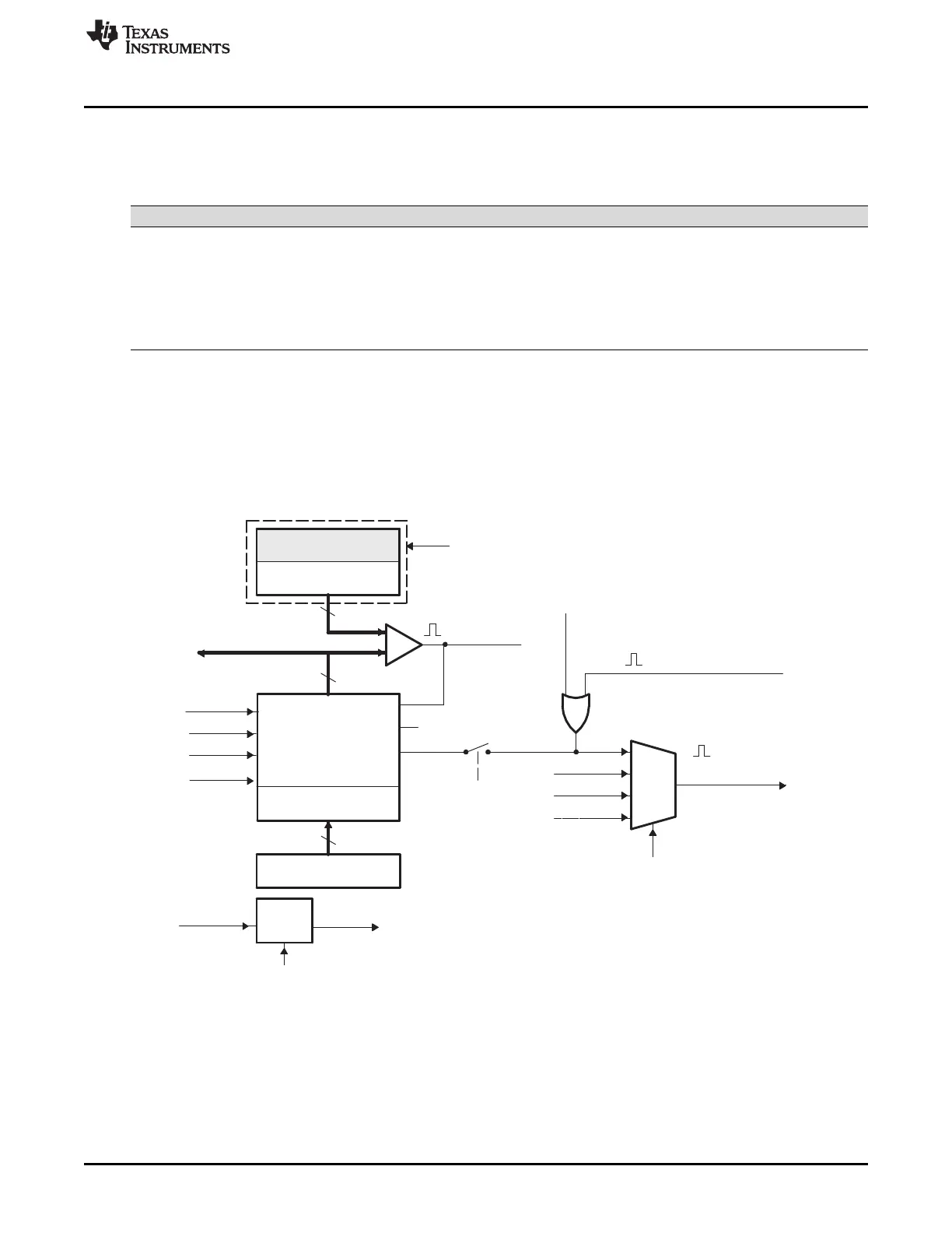
Figure 14-5 shows the critical signals and registers of the time-base submodule. Table 14-4 provides
descriptions of the key signals associated with the time-base submodule.
Figure 14-5. Time-Base Submodule Signals and Registers