d
7
6
5
I2C
prescaler
Prescaledmoduleclock
−−MUST besetto6.7−13.3MHz
I2Cinputclock
Registerbits
(ICPSC[IPSC])
I2Cclock
dividers
Registerbits
(ICCLKL[ICCL]),
(ICCLKH[ICCH])
I2C input clock frequency
(IPSC+1)
I2Cmodule
I2CserialclockonI2Cx_SCL pin
ToI2Cbus
I2C serial clock frequency=
prescaled module clock frequency
(ICCL +d)+(ICCH+d)
WhereddependsonIPSCvalueinICPSC:
IPSCvalue
0
1
2h−FFh
Prescaledmoduleclockfrequency=
Architecture
www.ti.com
894
SPRUH91D–March 2013–Revised September 2016
Submit Documentation Feedback
Copyright © 2013–2016, Texas Instruments Incorporated
Inter-Integrated Circuit (I2C) Module
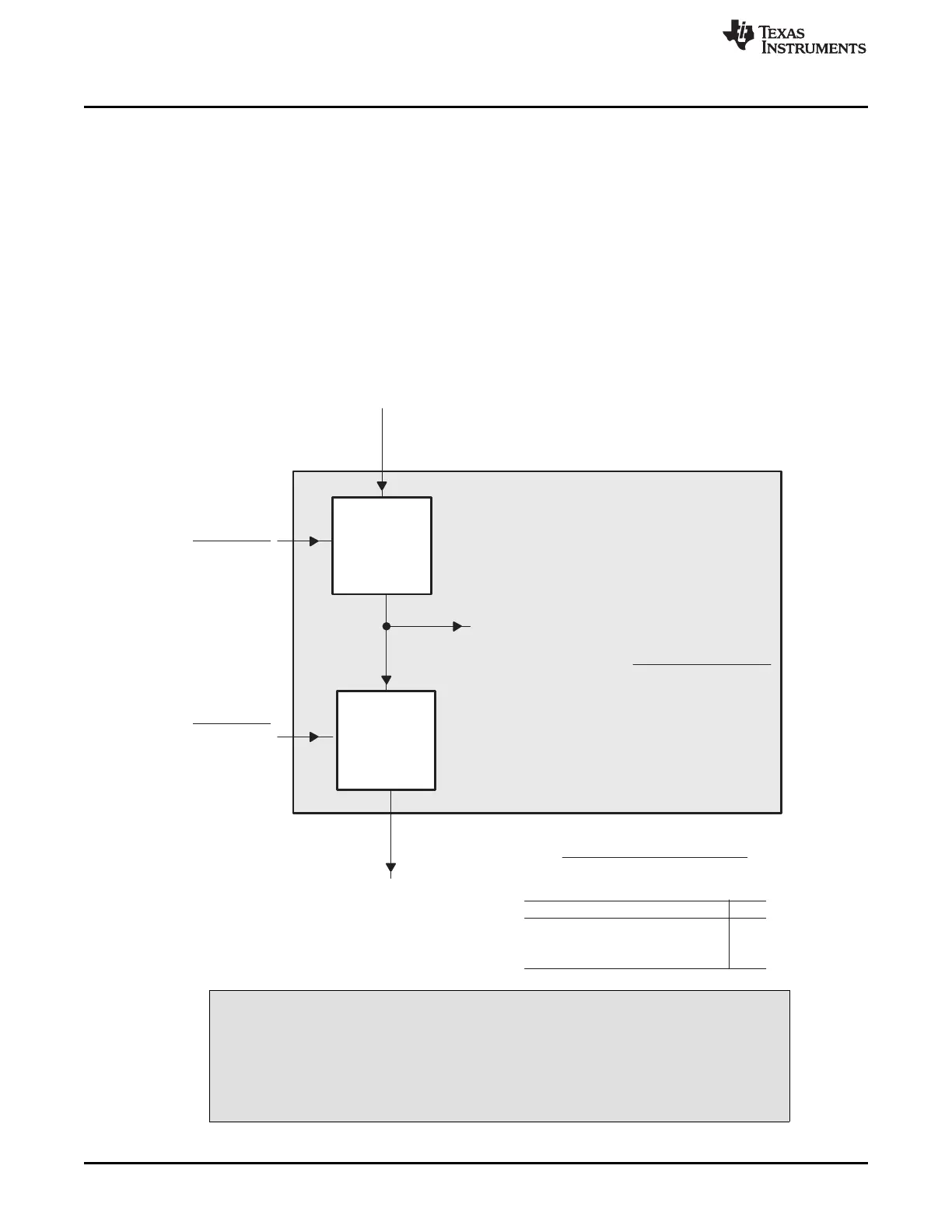
22.2.2 Clock Generation
As shown in Figure 22-3, I2C input clock is fed to the I2C module. A programmable prescaler (IPSC bit in
ICPSC) in the I2C module divides down the I2C input clock to produce a prescaled module clock. The
prescaled module clock must be operated within the range of 6.7 to 13.3 MHz. The I2C clock dividers
divide-down the high (ICCH bit in ICCLKH) and low portions (ICCL bit in ICCLKL) of the prescaled module
clock signal to produce the I2C serial clock, which appears on the I2Cx_SCL pin when the I2C module is
configured to be a master on the I2C bus.
The prescaler (IPSC bit in ICPSC) must only be initialized while the I2C module is in the reset state
(IRS = 0 in ICMDR). The prescaled frequency only takes effect when the IRS bit in ICMDR is changed to
1. Changing the IPSC bit in ICPSC while IRS = 1 in ICMDR has no effect. Likewise, you must configure
the I2C clock dividers (ICCH bit in ICCLKH and ICCL bit in ICCLKL) while the I2C module is still in reset
(IRS = 0 in ICMDR).
Figure 22-3. Clocking Diagram for the I2C Peripheral
CAUTION
Prescaled Module Clock Frequency Range:
The I2C module must be operated with a prescaled module clock frequency of
6.7 to 13.3 MHz. The I2C prescaler register (ICPSC) must be configured to this
frequency range.