CTR=0
CTR=CMPB
X
En
Φ=0°
SyncOut
Phase reg
Ext SyncIn
(optional)
EPWM1A
EPWM1B
SyncOut
Phase reg
CTR=CMPB
CTR=0
X
Φ=X
En
EPWM2B
EPWM2A
Slave
Master
Buck #1
Vout1Vin1
EPWM1A
Buck #2
Vin2
EPWM1B
Vout2
Buck #4
Buck #3
Vin3
EPWM2B
Vin4
EPWM2A
Vout3
Vout4
SyncIn
SyncIn
Applications to Power Topologies
www.ti.com
352
SPRUH91D–March 2013–Revised September 2016
Submit Documentation Feedback
Copyright © 2013–2016, Texas Instruments Incorporated
Enhanced High-Resolution Pulse-Width Modulator (eHRPWM)
Example 14-3. Configuration for Example in Figure 14-52
// Run Time (Note: Example execution of one run-time instance)
//=========================================================
EPwm1Regs.CMPA.half.CMPA = 700; // adjust duty for output EPWM1A
EPwm2Regs.CMPA.half.CMPA = 700; // adjust duty for output EPWM2A
EPwm3Regs.CMPA.half.CMPA = 500; // adjust duty for output EPWM3A
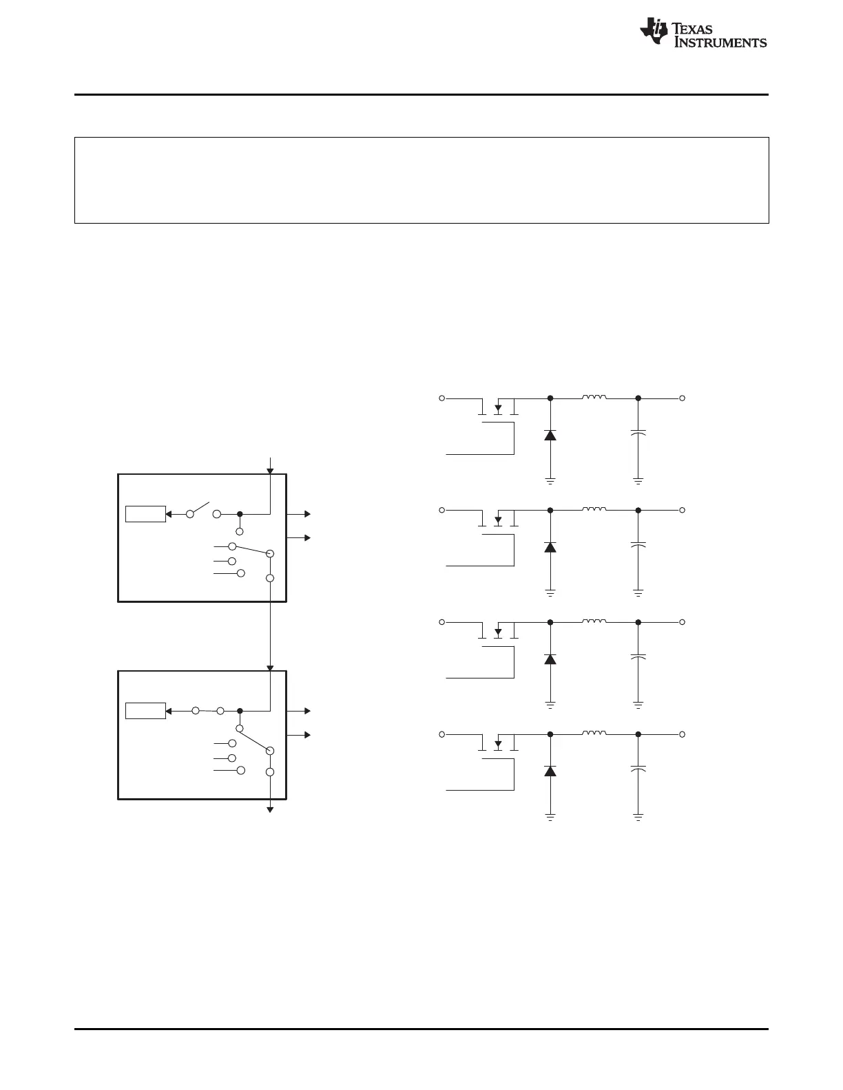
14.3.4 Controlling Multiple Buck Converters With Same Frequencies
If synchronization is a requirement, ePWM module 2 can be configured as a slave and can operate at
integer multiple (N) frequencies of module 1. The sync signal from master to slave ensures these modules
remain locked. Figure 14-53 shows such a configuration; Figure 14-54 shows the waveforms generated by
the configuration.
Figure 14-53. Control of Four Buck Stages. (Note: F
PWM2
= N × F
PWM1
)