Registers
www.ti.com
536
SPRUH91D–March 2013–Revised September 2016
Submit Documentation Feedback
Copyright © 2013–2016, Texas Instruments Incorporated
Enhanced Direct Memory Access (EDMA3) Controller
16.4.2.6 Interrupt Registers
All DMA/QDMA channels can be set to assert an EDMA3CC completion interrupt to the CPU on transfer
completion, by appropriately configuring the PaRAM entry associated with the channels. The following
registers are used for the transfer completion interrupt reporting/generating by the EDMA3CC. See
Section 16.2.9 for more details on EDMA3CC completion interrupt generation.
16.4.2.6.1 Interrupt Enable Registers (IER)
Interrupt enable register (IER) is used to enable/disable the transfer completion interrupt generation by the
EDMA3CC for all DMA/QDMA channels. The IER cannot be written to directly. To set any interrupt bit in
IER, a 1 must be written to the corresponding interrupt bit in the interrupt enable set registers (IESR).
Similarly, to clear any interrupt bit in IER, a 1 must be written to the corresponding interrupt bit in the
interrupt enable clear register (IECR).
The IER is shown in Figure 16-70 and described in Table 16-49.
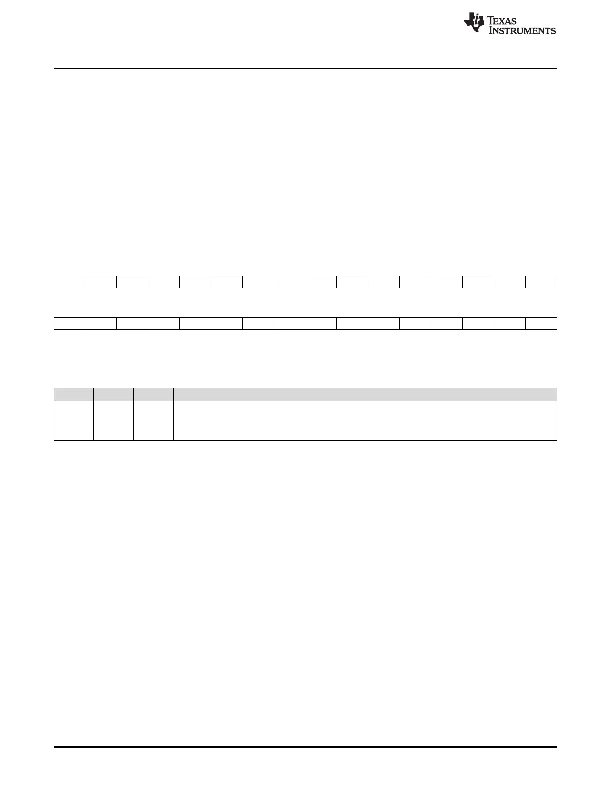
Figure 16-70. Interrupt Enable Register (IER)
31 30 29 28 27 26 25 24 23 22 21 20 19 18 17 16
I31 I30 I29 I28 I27I I26 I25 I24 I23 I22 I21 I20 I19 I18 I17 I16
R-0 R-0 R-0 R-0 R-0 R-0 R-0 R-0 R-0 R-0 R-0 R-0 R-0 R-0 R-0 R-0
15 14 13 12 11 10 9 8 7 6 5 4 3 2 1 0
I15 I14 I13 I12 I11 I10 I9 I8 I7 I6 I5 I4 I3 I2 I1 I0
R-0 R-0 R-0 R-0 R-0 R-0 R-0 R-0 R-0 R-0 R-0 R-0 R-0 R-0 R-0 R-0
LEGEND: R = Read only; -n = value after reset
Table 16-49. Interrupt Enable Register (IER) Field Descriptions
Bit Field Value Description
31-0 En Interrupt enable for channels 0-31.
0 Interrupt is not enabled.
1 Interrupt is enabled.

 Loading...


