Switched Central Resource (SCR)
BOOT ROM
256KB L2 RAM
32KB
L1 RAM
32KB
L1 Pgm
AET
C674x
DSP CPU
DSP Subsystem
JTAG Interface
Serial Interfaces
I C
(2)
2
SPI
(2)
UART
(3)
Audio Ports
McASP
w/FIFO
(2)
DMA
Peripherals
External Memory Interfaces
Connectivity
EDMA3
Control Timers
eHRPWM
(3)
eCAP
(3)
eQEP
(2)
(10/100)
EMAC
(RMII)
MDIO
USB2.0
OTG Ctlr
PHY
MMC/SD
(8b)
EMIFA(8b)
NAND/Flash
EMIFB
SDRAM Only
(16b)
GPIO
PRU
Subsystem
System Control
Input
Clock(s)
Power/Sleep
Controller
Memory
Protection
Pin
Multiplexing
PLL/Clock
Generator
w/OSC
General-
Purpose
Timer
General-
Purpose
Timer
(Watchdog)
Introduction
www.ti.com
66
SPRUH91D–March 2013–Revised September 2016
Submit Documentation Feedback
Copyright © 2013–2016, Texas Instruments Incorporated
Overview
1.1 Introduction
The C6745/C6747 DSP efficiently handles communication and audio processing tasks. The C6745/C6747
DSP consists of the following primary components:
• DSP subsystem and associated memories
• A set of I/O peripherals
• A powerful DMA subsystem and SDRAM EMIF interface
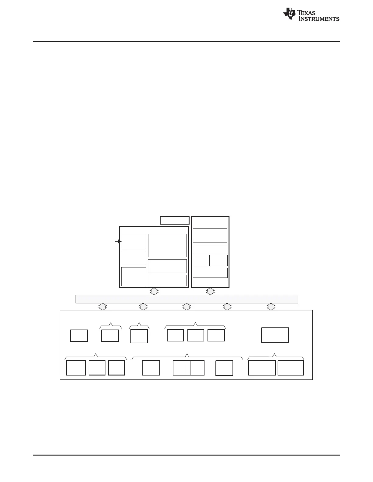
Block Diagram
A block diagram for the C6745 DSP is shown in TMS320C6745 DSP Block Diagram. A block diagram for
the C6747 DSP is shown in TMS320C6747 DSP Block Diagram.
DSP Subsystem
The DSP subsystem (DSPSS) includes TI’s standard TMS320C674x megamodule and several blocks of
internal memory (L1P, L1D, and L2). The DSP Subsystem chapter describes the DSPSS components.
DMA Subsystem
The DMA subsystem includes two instances of the enhanced DMA controller (EDMA3). For more
information, see the Enhanced Direct Memory Access (EDMA3) Controller chapter.
TMS320C6745 DSP Block Diagram
Note: Not all peripherals are available at the same time due to multiplexing.