ICXSR ICDXR
ICRSR ICDRR
Clock
synchronizer
Prescaler
Noise filters
Arbitrator
I2C INT
ICREVT
Peripheral data bus
Interrupt
to CPU
Sync events to
EDMA controller
I2Cx_SDA
I2Cx_SCL
Control/status
registers
CPU
EDMA
I2C peripheral
ICXEVT
Introduction
www.ti.com
892
SPRUH91D–March 2013–Revised September 2016
Submit Documentation Feedback
Copyright © 2013–2016, Texas Instruments Incorporated
Inter-Integrated Circuit (I2C) Module
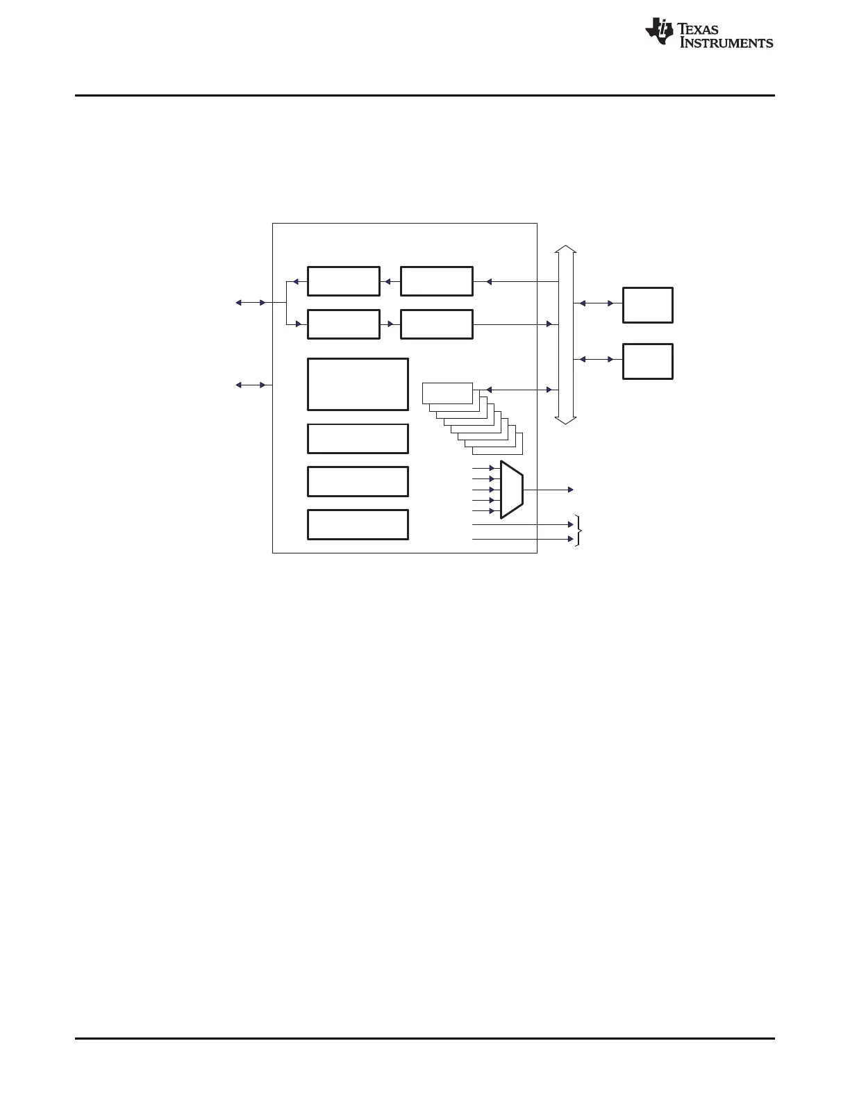
22.1.3 Functional Block Diagram
A block diagram of the I2C peripheral is shown in Figure 24-1. Refer to Section 22.2 for detailed
information about the architecture of the I2C peripheral.
Figure 22-1. I2C Peripheral Block Diagram
22.1.4 Industry Standard(s) Compliance Statement
The I2C peripheral is compliant with the Philips Semiconductors Inter-IC bus (I2C-bus) specification
version 2.1.