UHPI_HDS1
UHPI_HDS2
UHPI_HCS
UHPI_HRDY
Internal
HSTRB
Internal
HRDY
Architecture
www.ti.com
866
SPRUH91D–March 2013–Revised September 2016
Submit Documentation Feedback
Copyright © 2013–2016, Texas Instruments Incorporated
Host Port Interface (HPI)
21.2.6.4 UHPI_HDS2, UHPI_HDS1, and UHPI_HCS: Data Strobing and Chip Selection
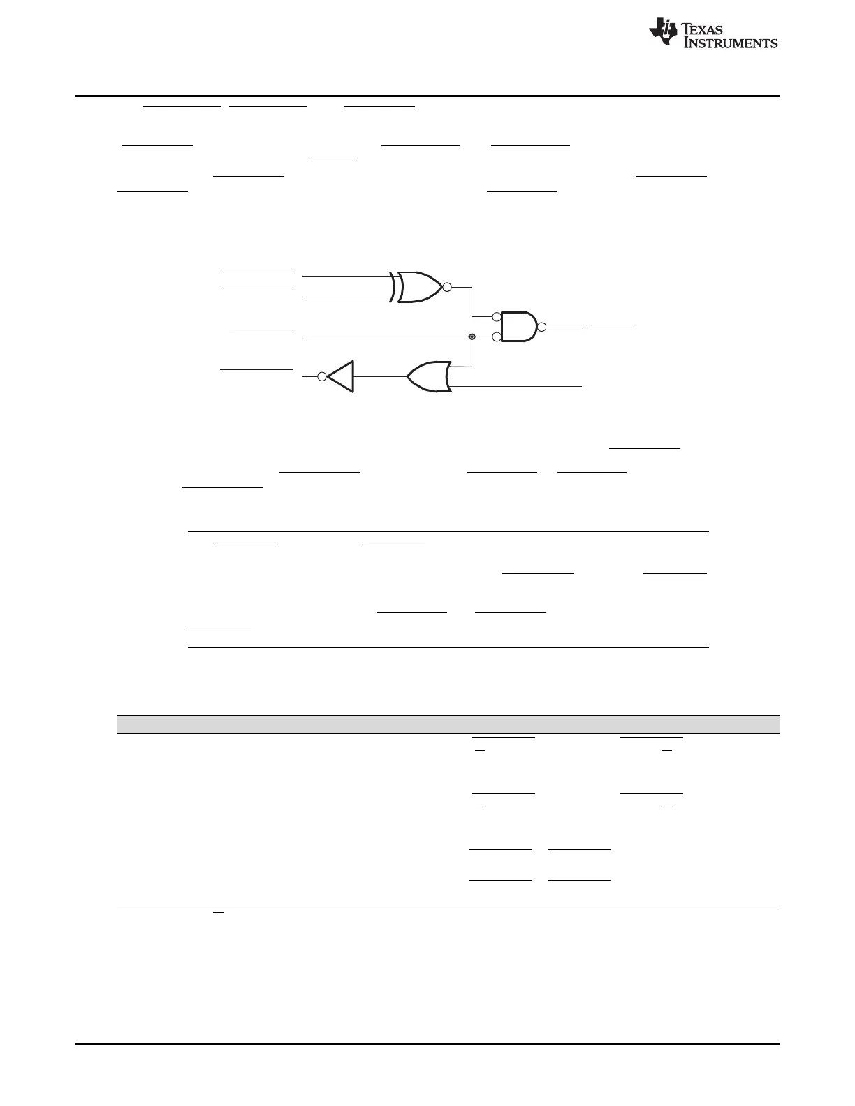
As shown in Figure 21-3, the strobing logic is a function of three key inputs: the chip select pin
(UHPI_HCS) and two data strobe signals (UHPI_HDS1 and UHPI_HDS2). The internal strobe signal,
which is referred to as internal HSTRB throughout this document, functions as the actual strobe signal
inside the HPI. UHPI_HCS must be low (HPI selected) during strobe activity on the UHPI_HDS pins. If
UHPI_HCS remains high (HPI not selected), activity on the UHPI_HDS pins is ignored.
Figure 21-3. HPI Strobe and Select Logic
Strobe connections between the host and the HPI depend in part on the number and types of strobe pins
available on the host. Table 21-3 describes some options for connecting to the UHPI_HDS pins.
Notice in Figure 21-3 that UHPI_HRDY is also gated by UHPI_HCS. If UHPI_HCS goes high (HPI not
selected), UHPI_HRDY goes low, regardless of whether the current internal transfer is completed in the
processor.
NOTE: The UHPI_HCS input and one UHPI_HDS strobe input can be tied together and driven with
a single strobe signal from the host. This technique selects the HPI and provides the strobe,
simultaneously. When using this method, be aware that UHPI_HRDY is gated by UHPI_HCS
as previously described.
It is not recommended to tie both UHPI_HDS1 and UHPI_HDS2 to static logic levels and use
UHPI_HCS as a strobe.
(1)
The UHPI_HR/W signal could be driven by a host address line in this case.
Table 21-3. Options for Connecting Host and HPI Data Strobe Pins
Available Host Data Strobe Pins Connections to HPI Data Strobe Pins
Host has separate read and write strobe
pins, both active-low
Connect one strobe pin to UHPI_HDS1 and the other to UHPI_HDS2
(1)
. Since such a
host might not provide a R/W line, take care to satisfy UHPI_HR/W timings as stated in
your device-specific data manual. This could possibly be done using a host address
line.
Host has separate read and write strobe
pins, both active-high
Connect one strobe pin to UHPI_HDS1 and the other to UHPI_HDS2
(1)
. Since such a
host might not provide a R/W line, take care to satisfy UHPI_HR/W timings as stated in
your device-specific data manual. This could possibly be done using a host address
line.
Host has one active-low strobe pin Connect the strobe pin to UHPI_HDS1 or UHPI_HDS2, and connect the other pin to
logic-level 1.
Host has one active-high strobe pin Connect the strobe pin to UHPI_HDS1 or UHPI_HDS2, and connect the other strobe
pin to logic-level 0.















 To Next Page