Command/data
scheduler
CommandFIFO
WriteFIFO
ReadFIFO
Registers
Command
tomemory
WriteData
tomemory
Readdata
from
memory
Command
Data
www.ti.com
Architecture
799
SPRUH91D–March 2013–Revised September 2016
Submit Documentation Feedback
Copyright © 2013–2016, Texas Instruments Incorporated
External Memory Interface B (EMIFB)
19.2.6.11 SDRAM Memory Controller FIFO and Prioritization Considerations
To move data efficiently from on-chip resources to external SDRAM memory, the EMIFB memory
controller makes use of a command FIFO, a write FIFO, a read FIFO, and command and data schedulers.
Table 19-17 describes the purpose of each FIFO.
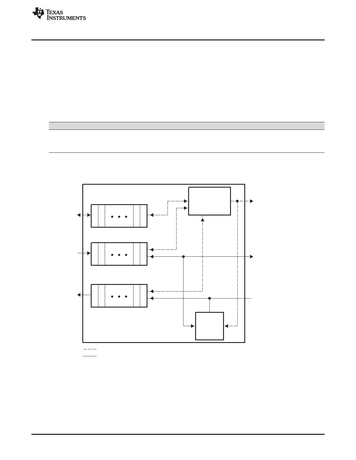
Figure 19-8 shows the block diagram of the SDRAM memory controller FIFOs. Commands, write data,
and read data arrive at the SDRAM memory controller parallel to each other. The same peripheral bus is
used to write and read data from external memory as well as internal memory-mapped registers.
Table 19-17. SDRAM Memory Controller FIFO Description
FIFO Description Depth (32-bit words)
Command Stores all commands coming from on-chip requesters 7
Write Stores write data coming from on-chip requesters to memory 11
Read Stores read data coming from memory to on-chip requesters 15
Figure 19-8. EMIFB Memory Controller FIFO Block Diagram