1180 0800h A4i
A12i
A3iA2iA1i
A9i A10i A11i
A7iA6iA5i
A13i ... ...
A8i
B6i
B9i B10i B11i B12i B13i ...
B1i B2i B3i B4i B5i
...
B8i
B7i
..B5..A5..B4..A4..B3..A3..B2..A2..B1..A1
1180 0880h
B6o
A6o
B2oB1o
B9o B10o
A9i A10i
B5oB4oB3o
B11o B12o B13o ...
A11i A12i A13i ...
A1o A2o A3o A4o A5o
B7o B8o
...
...
A8oA7o1180 1800h
1180 1880h
A1..B1..A2..B2..A3..B3..A4..B4..A5..B5
Pong
DRR
RBR
RSR
A11i
B3o
B11oB9o B10o
B1o
A9i
B2o
A10i
B13oB12o ...
A13i
B5oB4o
A12i
B6o
...
B11i
B3i
A3oA1o A2o
B9i
B1i
B10i
B2i
A5o
A4o A6o
B13i
B5i
B12i
B4i
...
B6i
...
B8oB7o
...
A8oA7o
...
B7i B8i
A3i
A11iA9i
A1i
A10i
A2i A5i
A13iA12i
A4i
...
A6i
Ping
...
A7i A8i
REVT
01D0 0000h
DXR
XEVT
XSR
01D0 0004h
1180 0000h
1180 0080h
1180 1000h
1180 1080h
www.ti.com
Transfer Examples
495
SPRUH91D–March 2013–Revised September 2016
Submit Documentation Feedback
Copyright © 2013–2016, Texas Instruments Incorporated
Enhanced Direct Memory Access (EDMA3) Controller
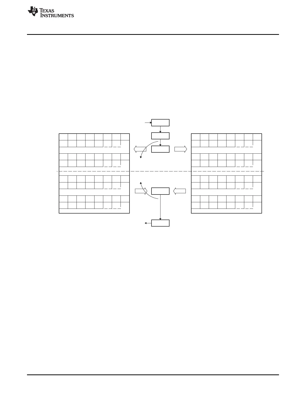
16.3.4.4.1 Synchronization with the CPU
In order to utilize the ping-pong buffering technique, the system must signal the CPU when to begin to
access the new data set. After the CPU finishes processing an input buffer (ping), it waits for the EDMA3
to complete before switching to the alternate (pong) buffer. In this example, both channels provide their
channel numbers as their report word and set the TCINTEN bit to 1 to generate an interrupt after
completion. When channel 3 fills an input buffer, the E3 bit in the interrupt pending register (IPR) is set to
1; when channel 2 empties an output buffer, the E2 bit in IPR is set to 1. The CPU must manually clear
these bits. With the channel parameters set, the CPU polls IPR to determine when to switch. The EDMA3
and CPU could alternatively be configured such that the channel completion interrupts the CPU. By doing
this, the CPU could service a background task while waiting for the EDMA3 to complete.
Figure 16-28. Ping-Pong Buffering for McBSP Data Example