www.ti.com
Registers
765
SPRUH91D–March 2013–Revised September 2016
Submit Documentation Feedback
Copyright © 2013–2016, Texas Instruments Incorporated
External Memory Interface A (EMIFA)
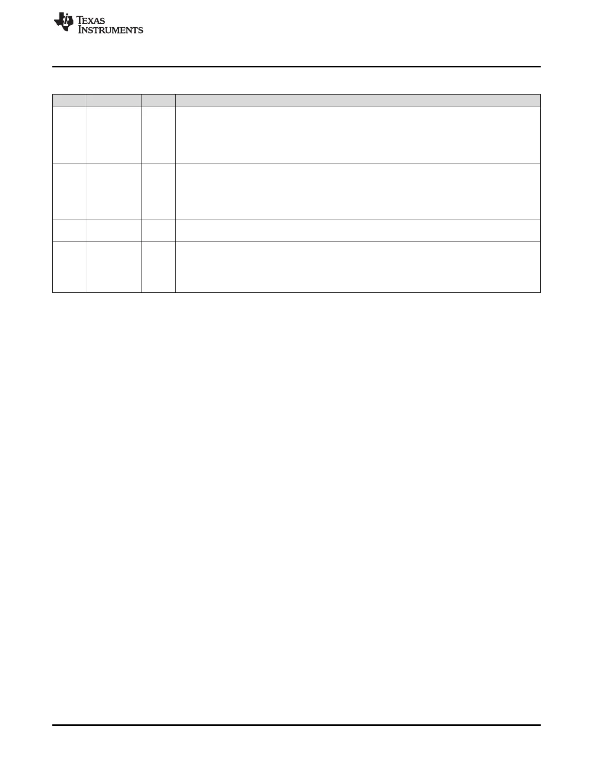
Table 18-53. Asynchronous n Configuration Register (CEnCFG) Field Descriptions (continued)
Bit Field Value Description
12-7 R_STROBE 0-3Fh Read strobe width in the format n - 1, where n = number of EMA_CLK cycles. See Section 18.2.5.3 for
details.
0h = Divide-by-1
1h = Divide-by-2
…
2h – 3Fh = Divide-by-3 to Divide-by-64
6-4 R_HOLD 0-7h Read hold width in the format n - 1, where n = number of EMA_CLK cycles. See Section 18.2.5.3 for
details.
0h = Divide-by-1
1h = Divide-by-2
…
2h – 7h = Divide-by-3 to Divide-by-8
3-2 TA 0-3h Minimum Turn-Around time. This field defines the minimum number of EMA_CLK cycles between reads
and writes, minus one cycle. See Section 18.2.5.3 for details.
1-0 ASIZE 0-3h Asynchronous Data Bus Width. This field defines the width of the asynchronous device's data bus.
0 8-bit data bus
1h 16-bit data bus
2h-3h Reserved
 Loading...


