www.ti.com
SYSCFG Registers
233
SPRUH91D–March 2013–Revised September 2016
Submit Documentation Feedback
Copyright © 2013–2016, Texas Instruments Incorporated
System Configuration (SYSCFG) Module
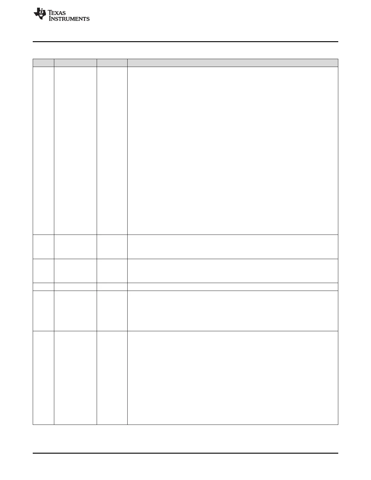
Table 10-46. Chip Configuration 1 Register (CFGCHIP1) Field Descriptions (continued)
Bit Field Value Description
21-17 CAP0SRC Selects the eCAP0 module event input.
0 eCAP0 Pin input
1h McASP0 TX DMA Event
2h McASP0 RX DMA Event
3h McASP1 TX DMA Event
4h McASP1 RX DMA Event
5h McASP2 TX DMA Event. This peripheral is not supported on the C6745 DSP.
6h McASP2 RX DMA Event. This peripheral is not supported on the C6745 DSP.
7h EMAC C0 RX Threshold Pulse Interrupt
8h EMAC C0 RX Pulse Interrupt
9h EMAC C0 TX Pulse Interrupt
Ah EMAC C0 Miscellaneous Interrupt
Bh EMAC C1 RX Threshold Pulse Interrupt
Ch EMAC C1 RX Pulse Interrupt
Dh EMAC C1 TX Pulse Interrupt
Eh EMAC C1 Miscellaneous Interrupt
Fh EMAC C2 RX Threshold Pulse Interrupt
10h EMAC C2 RX Pulse Interrupt
11h EMAC C2 TX Pulse Interrupt
12h EMAC C2 Miscellaneous Interrupt
13h-1Fh Reserved
16 HPIBYTEAD HPI Byte/Word Address Mode select. This peripheral is not supported on the C6745 DSP.
0 Host address is a word address.
1 Host address is a byte address.
15 HPIENA HPI Enable Bit. This peripheral is not supported on the C6745 DSP.
0 HPI is disabled.
1 HPI is enabled.
14-13 Reserved 0 Reserved. Always read as 0.
12 TBCLKSYNC eHRPWM Module Time Base Clock (TBCLK) Synchronization. Allows you to globally
synchronize all enabled eHRPWM modules to the time base clock (TBCLK).
0 Time base clock (TBCLK) within each enabled eHRPWM module is stopped.
1 All enabled eHRPWM module clocks are started with the first rising edge of TBCLK aligned. For
perfectly synchronized TBCLKs, the prescaler bits in the TBCTL register of each eHRPWM
module must be set identically.
11-8 AMUTESEL2 Selects the source of McASP2 AMUTEIN signal. This peripheral is not supported on the
C6745 DSP.
0 Drive McASP2 AMUTEIN signal low
1h GPIO Interrupt from Bank 0
2h GPIO Interrupt from Bank 1
3h GPIO Interrupt from Bank 2
4h GPIO Interrupt from Bank 3
5h GPIO Interrupt from Bank 4
6h GPIO Interrupt from Bank 5
7h GPIO Interrupt from Bank 6
8h GPIO Interrupt from Bank 7
9h-Fh Reserved
 Loading...


