Provision Ring cross-connections using the
aided cross-connection tool
752
WebEML User Manual
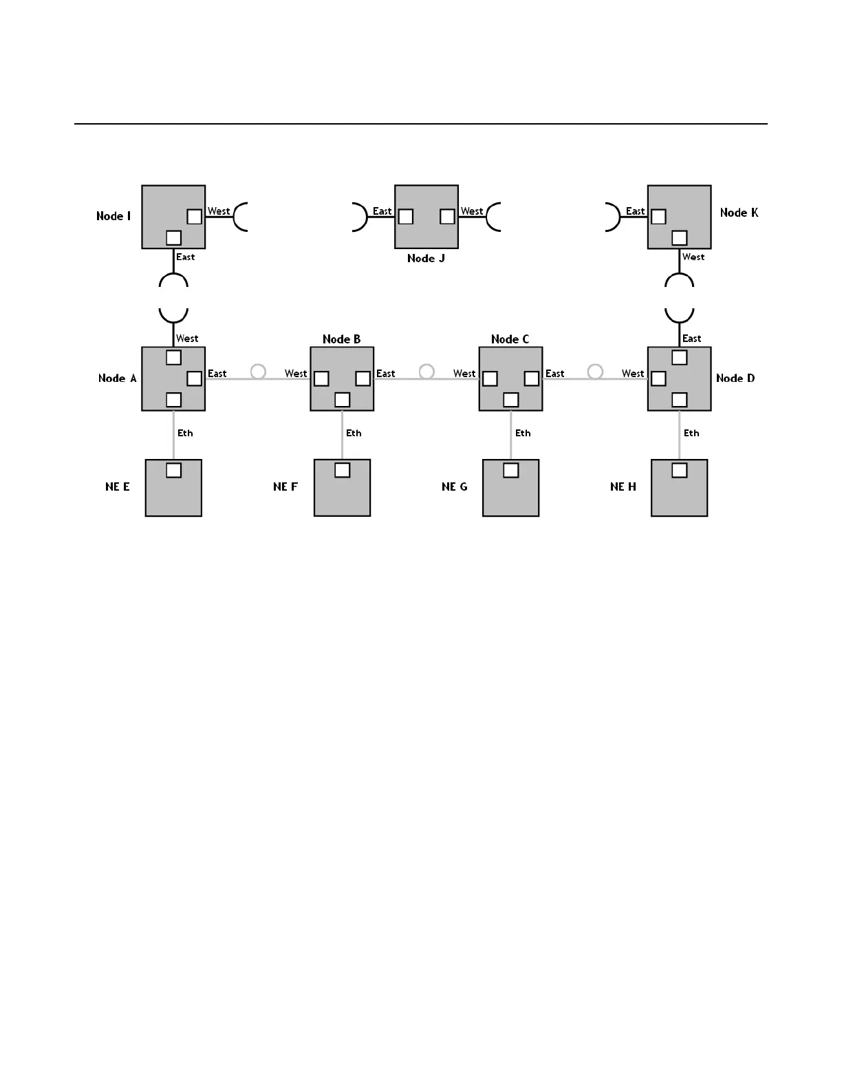
Figure 566 Sample mixed fiber/microwave Ring
The sample Ring consists of nodes A, B, C, D, I, J and K. Nodes A, B, C and D are
members of the Ring’s fiber chain. NEs E, F, G, and H connect to the Ring’s fiber
chain using Ethernet connections.
The list of Ring nodes belonging to the fiber chain in the description tool must follow
the exact sequence of nodes along the chain:
• The First Node must be the one which has the Radio interface (L1 LAG) as West
Ring Port and the optical User Ethernet interface as East Ring Port (Node A).
• The Last Node must be the one which has the Radio interface (L1 LAG) as East
Ring Port and the optical User Ethernet interface as West Ring Port (Node D).
The presence of a Cross-connection Gateway, a Ring Node where all TDM flows are
aggregated, can be selected as:
• No Gateway, when there is no node in the whole Ring that aggregates TDM
flows
• Outside Ring’s Fiber Chain, when there is a Ring node that aggregates TDM
flows but it is outside the Ring’s Fiber Chain
• Specific Ring node, when there is a Ring Node which aggregates TDM flows and
this node is inside the Ring’s Fiber Chain
Release 7.0.0 3DB 19286 ACAA Issue 01