www.ti.com
General-Purpose Input/Output (GPIO)
121
SPRUI07–March 2020
Submit Documentation Feedback
Copyright © 2020, Texas Instruments Incorporated
System Control and Interrupts
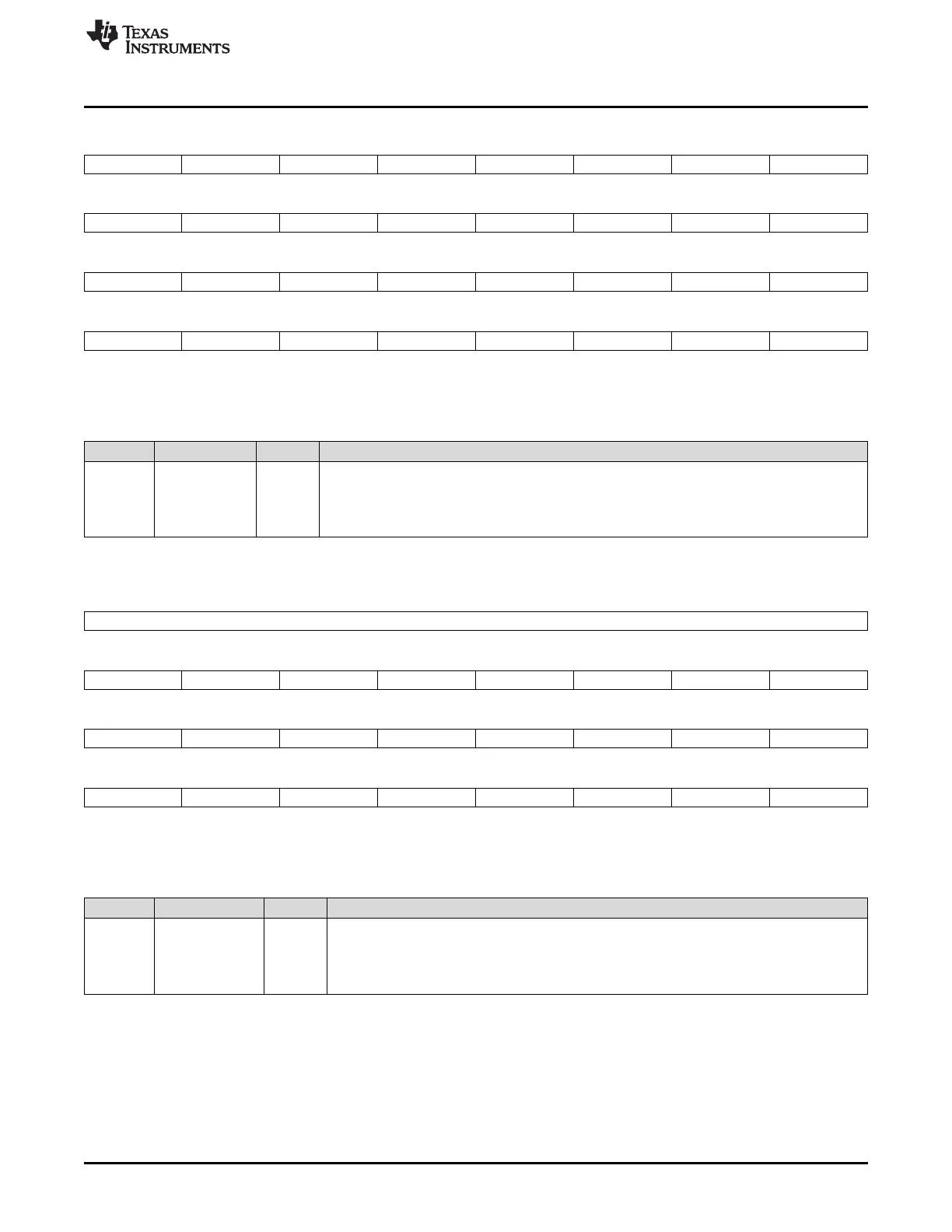
Figure 1-63. GPIO Port B Pullup Disable (GPBPUD) Registers
31 30 29 28 27 26 25 24
GPIO63 GPIO62 GPIO61 GPIO60 GPIO59 GPIO58 GPIO57 GPIO56
R/W-0 R/W-0 R/W-0 R/W-0 R/W-0 R/W-0 R/W-0 R/W-0
23 22 21 20 19 18 17 16
GPIO55 GPIO54 GPIO53 GPIO52 GPIO51 GPIO50 GPIO49 GPIO48
R/W-0 R/W-0 R/W-0 R/W-0 R/W-0 R/W-0 R/W-0 R/W-0
15 14 13 12 11 10 9 8
GPIO47 GPIO46 GPIO45 GPIO44 GPIO43 GPIO42 GPIO41 GPIO40
R/W-0 R/W-0 R/W-0 R/W-0 R/W-0 R/W-0 R/W-0 R/W-0
7 6 5 4 3 2 1 0
GPIO39 GPIO38 GPIO37 GPIO36 GPIO35 GPIO34 GPIO33 GPIO32
R/W-0 R/W-0 R/W-0 R/W-0 R/W-0 R/W-0 R/W-0 R/W-0
LEGEND: R/W = Read/Write; R = Read only; -n = value after reset
(1)
This register is EALLOW protected. See Section 1.5.2 for more information.
Table 1-66. GPIO Port B Internal Pullup Disable (GPBPUD) Register Field Descriptions
Bits Field Value Description
(1)
31-0 GPIO63-
GPIO32
Configure the internal pullup resister on the selected GPIO Port B pin. Each GPIO pin
corresponds to one bit in this register.
0 Enable the internal pullup on the specified pin. (default)
1 Disable the internal pullup on the specified pin.
Figure 1-64. GPIO Port C Pullup Disable (GPCPUD) Registers
31 24
Reserved
R/W-0
23 22 21 20 19 18 17 16
GPIO87 GPIO86 GPIO85 GPIO84 GPIO83 GPIO82 GPIO81 GPIO80
R/W-0 R/W-0 R/W-0 R/W-0 R/W-0 R/W-0 R/W-0 R/W-0
15 14 13 12 11 10 9 8
GPIO79 GPIO78 GPIO77 GPIO76 GPIO75 GPIO74 GPIO73 GPIO72
R/W-0 R/W-0 R/W-0 R/W-0 R/W-0 R/W-0 R/W-0 R/W-0
7 6 5 4 3 2 1 0
GPIO71 GPIO70 GPIO69 GPIO68 GPIO67 GPIO66 GPIO65 GPIO64
R/W-0 R/W-0 R/W-0 R/W-0 R/W-0 R/W-0 R/W-0 R/W-0
LEGEND: R/W = Read/Write; R = Read only; -n = value after reset
(1)
This register is EALLOW protected. See Section 1.5.2 for more information.
Table 1-67. GPIO Port C Internal Pullup Disable (GPCPUD) Register Field Descriptions
Bits Field Value Description
(1)
31-0 GPIO87-GPIO64 Configure the internal pullup resister on the selected GPIO Port C pin. Each GPIO pin
corresponds to one bit in this register.
0 Enable the internal pullup on the specified pin.
1 Disable the internal pullup on the specified pin.
The GPIO data registers indicate the current status of the GPIO pin, irrespective of which mode the pin is
in. Writing to this register will set the respective GPIO pin high or low if the pin is enabled as a GPIO
output, otherwise the value written is latched but ignored. The state of the output register latch will remain
in its current state until the next write operation. A reset will clear all bits and latched values to zero. The
value read from the GPxDAT registers reflect the state of the pin (after qualification), not the state of the
output latch of the GPxDAT register.
 Loading...