Read first word (W1)
W1=
0x10AA
?
No
16-bit data size
Yes
Read EntryPoint address
Read second word
(W2) and discard
upper 8-bits
?
0x08AA
W2:W1=
Yes
No
8-bit
DataSize
Data format error
Return
FLASH_ENTRY_POINT
Read BlockSize (R)
?
R=0
No
Yes
Return
EntryPoint
Read BlockAddress
Transfer R words of
data from source to
destination
www.ti.com
Bootloader Features
183
SPRUI07–March 2020
Submit Documentation Feedback
Copyright © 2020, Texas Instruments Incorporated
Boot ROM
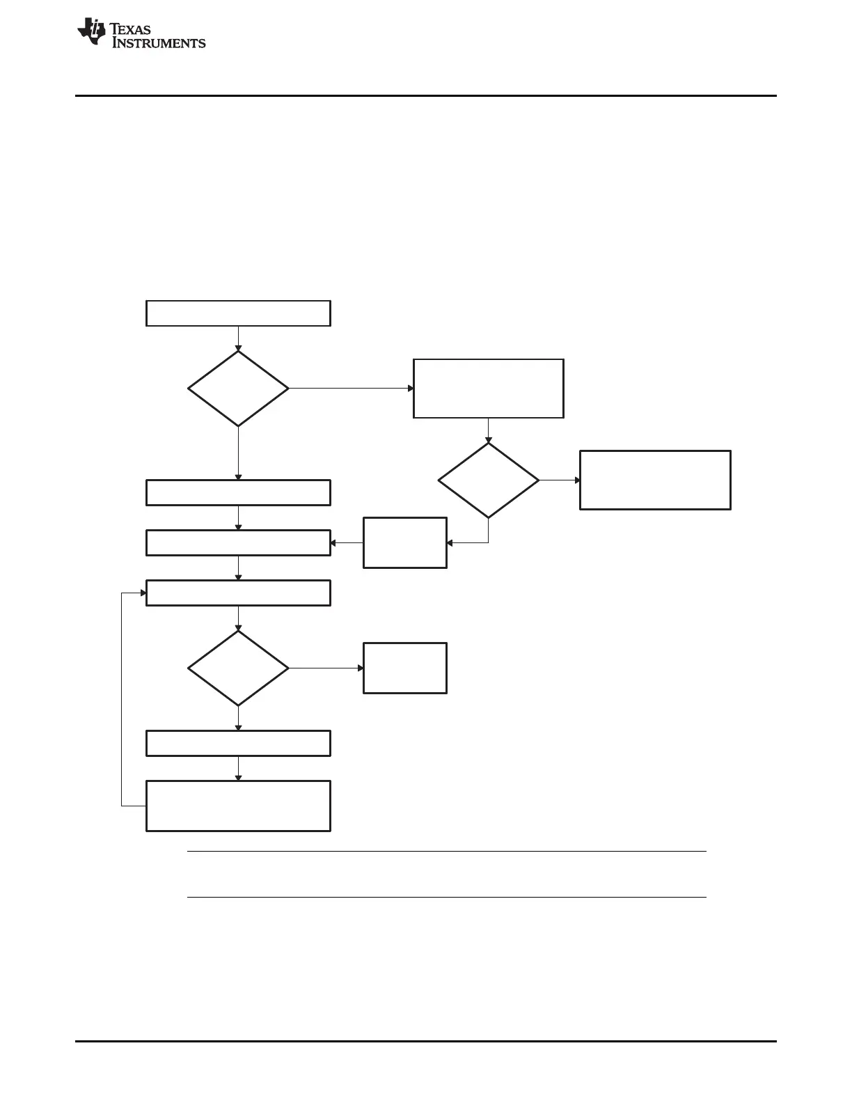
2.2.11 Basic Transfer Procedure
Figure 2-11 illustrates the basic process a bootloader uses to transfer data and start program execution.
This process occurs after the bootloader determines the valid boot mode selected by the state of the
GPIO pins. The loader first compares the first value sent by the host against the 16-bit key value of
0x10AA. If the value fetched does not match then the loader will read a second value. This value will be
combined with the first value to form a word. This will then be checked against the 8-bit key value of
0x08AA. If the loader finds that the header does not match either the 8-bit or 16-bit key value, or if the
value is not valid for the given boot mode then the load will abort.
In this case, the loader will return the entry point address for the flash to the calling routine.
Figure 2-11. Bootloader Basic Transfer Procedure
NOTE: See the info specific to a particular bootloader for any limitations. In 8-bit mode, the LSB of
the 16-bit word is read first followed by the MSB.
2.2.12 InitBoot Assembly Routine
The first routine called after reset is the InitBoot assembly routine. This routine initializes the device for
operation in C28x object mode. InitBoot also performs a dummy read of the Code Security Module (CSM)
password locations. If the CSM passwords are erased (all 0xFFFFs) then this has the effect of unlocking
the CSM. Otherwise the CSM will remain locked and this dummy read of the password locations will have
no effect. This can be useful if you have a new device that you want to boot load.
 Loading...