SRC or DST
sync select
DMA channel x
processing logic
MODE.CHx[SYNCSEL]
Clear sync
Set
Latch
Clear
CONTROL.CHx
[SYNCCLR]
CONTROL.CHx
[SYNCERRCLR]
Clear
Set
Latch
Peripheral sync
CONTROL.CHx[SYNCFLG]
CONTROL.CHx
[SYNCFRC]
CONTROL.CHx
[SYNCERR]
MODE.CHx
[SYNCE]
00000
00001
00010
00011
11100
11101
0
SEQ1INT
N/A
N/A
N/A
N/A
.
.
MODE.CHx
[PERINTSEL]
www.ti.com
ADC Sync Feature
509
SPRUI07–March 2020
Submit Documentation Feedback
Copyright © 2020, Texas Instruments Incorporated
Direct Memory Access (DMA) Module
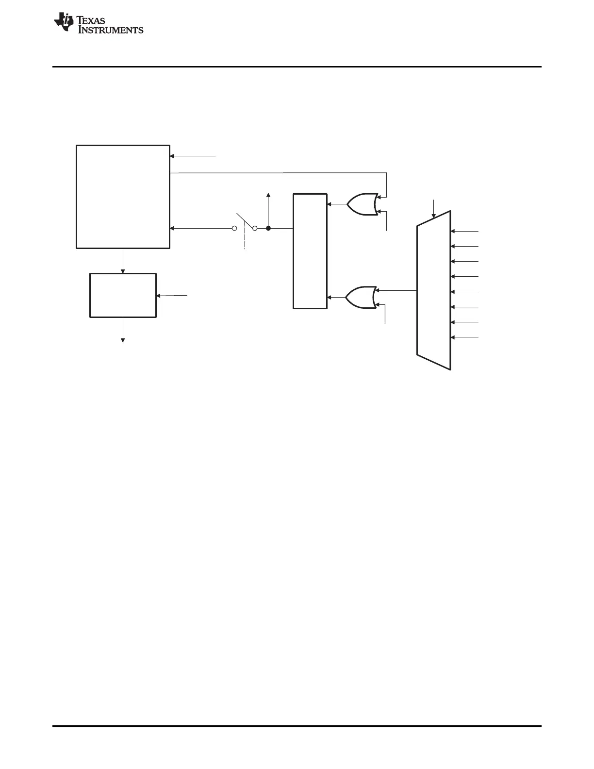
As shown in Figure 8-6, the synchronization source is chosen by the PERINTSEL bit field in the MODE
register. If the SYNC feature is enabled for the selected source and channel, the transfer for that channel
will not commence until reception of the first SYNC after the RUN bit is set. All peripheral interrupt triggers
are ignored up to the first SYNC event.
Figure 8-6. ADC Sync Input Diagram
 Loading...