CTR = CMPB
CTR = CMPA
CTR_Dir
CTR = 0
CTR = PRD
Dead
Band
(DB)
Counter
Compare
(CC)
Action
Qualifier
(AQ)
EPWMxB
EPWMxA
CTR = CMPB
CTR = 0
EPWMxINT
EPWMxSOCA
EPWMxSOCB
EPWMxA
EPWMxB
TZ1 to TZ6
CTR = CMPA
Time-Base
(TB)
CTR = PRD
CTR = 0
CTR_Dir
EPWMxSYNCI
EPWMxSYNCO
EPWMxTZINT
PWM-
chopper
(PC)
Event
Trigger
and
Interrupt
(ET)
Trip
Zone
(TZ)
GPIO
MUX
ADC
PIE
PIE
www.ti.com
ePWM Submodules
261
SPRUI07–March 2020
Submit Documentation Feedback
Copyright © 2020, Texas Instruments Incorporated
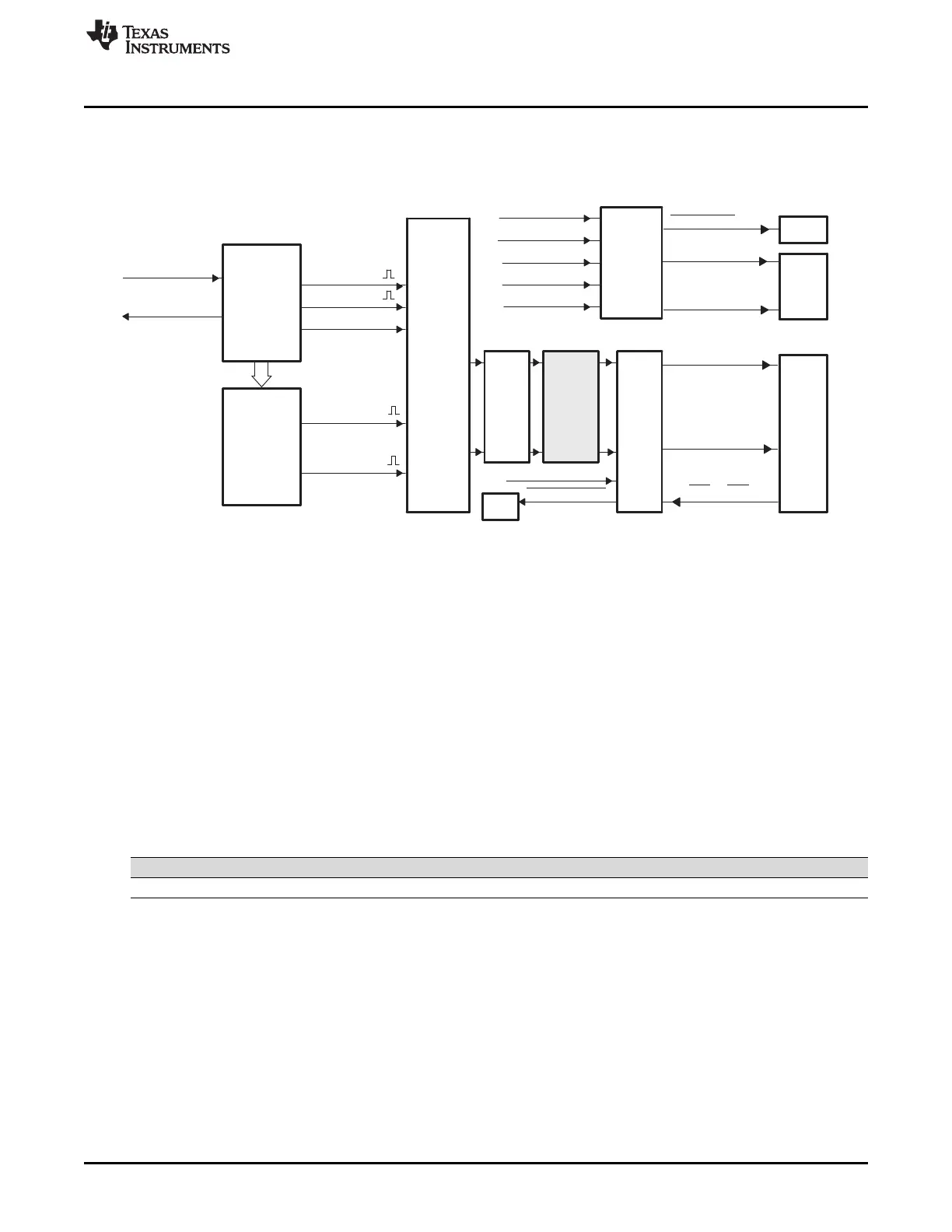
Enhanced Pulse Width Modulator (ePWM) Module
3.2.6 PWM-Chopper (PC) Submodule
Figure 3-31 illustrates the PWM-chopper (PC) submodule within the ePWM module.
Figure 3-31. PWM-Chopper Submodule
The PWM-chopper submodule allows a high-frequency carrier signal to modulate the PWM waveform
generated by the action-qualifier and dead-band submodules. This capability is important if you need
pulse transformer-based gate drivers to control the power switching elements.
3.2.6.1 Purpose of the PWM-Chopper Submodule
The key functions of the PWM-chopper submodule are:
• Programmable chopping (carrier) frequency
• Programmable pulse width of first pulse
• Programmable duty cycle of second and subsequent pulses
• Can be fully bypassed if not required
3.2.6.2 Controlling the PWM-Chopper Submodule
The PWM-chopper submodule operation is controlled via the registers in Table 3-16.
Table 3-16. PWM-Chopper Submodule Registers
mnemonic Address offset Shadowed Description
PCCTL 0x001E No PWM-chopper Control Register
3.2.6.3 Operational Highlights for the PWM-Chopper Submodule
Figure 3-32 shows the operational details of the PWM-chopper submodule. The carrier clock is derived
from SYSCLKOUT. Its frequency and duty cycle are controlled via the CHPFREQ and CHPDUTY bits in
the PCCTL register. The one-shot block is a feature that provides a high energy first pulse to ensure hard
and fast power switch turn on, while the subsequent pulses sustain pulses, ensuring the power switch
remains on. The one-shot width is programmed via the OSHTWTH bits. The PWM-chopper submodule
can be fully disabled (bypassed) via the CHPEN bit.
 Loading...