eQEP Registers
www.ti.com
424
SPRUI07–March 2020
Submit Documentation Feedback
Copyright © 2020, Texas Instruments Incorporated
Enhanced Quadrature Encoder Pulse (eQEP)
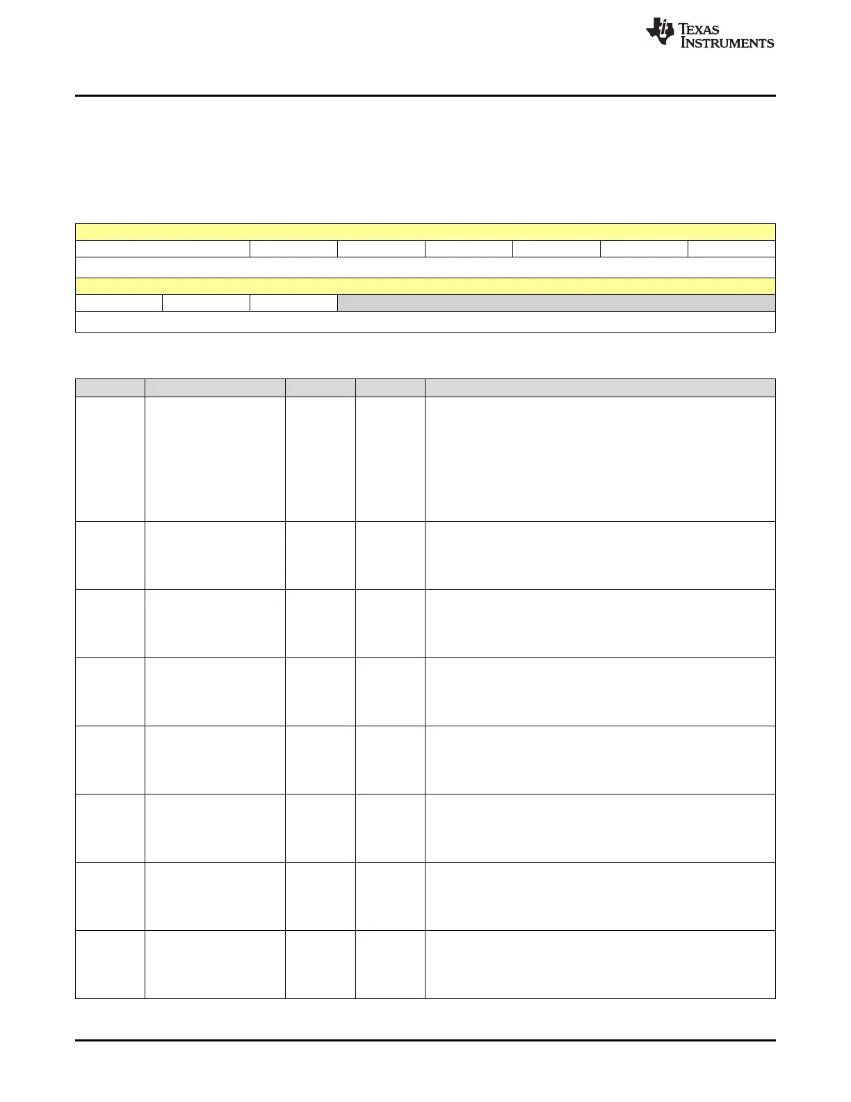
6.10.2.12 QDECCTL Register (Offset = 14h) [reset = 0h]
QDECCTL is shown in Figure 6-32 and described in Table 6-17.
Return to the Summary Table.
Quadrature Decoder Control
Figure 6-32. QDECCTL Register
15 14 13 12 11 10 9 8
QSRC SOEN SPSEL XCR SWAP IGATE QAP
R/W-0h R/W-0h R/W-0h R/W-0h R/W-0h R/W-0h R/W-0h
7 6 5 4 3 2 1 0
QBP QIP QSP RESERVED
R/W-0h R/W-0h R/W-0h R-0h
Table 6-17. QDECCTL Register Field Descriptions
Bit Field Type Reset Description
15-14 QSRC R/W 0h
Position-counter source selection
Reset type: SYSRSn
0h (R/W) = Quadrature count mode (QCLK = iCLK, QDIR = iDIR)
1h (R/W) = Direction-count mode (QCLK = xCLK, QDIR = xDIR)
2h (R/W) = UP count mode for frequency measurement (QCLK =
xCLK, QDIR = 1)
3h (R/W) = DOWN count mode for frequency measurement (QCLK
= xCLK, QDIR = 0)
13 SOEN R/W 0h
Sync output-enable
Reset type: SYSRSn
0h (R/W) = Disable position-compare sync output
1h (R/W) = Enable position-compare sync output
12 SPSEL R/W 0h
Sync output pin selection
Reset type: SYSRSn
0h (R/W) = Index pin is used for sync output
1h (R/W) = Strobe pin is used for sync output
11 XCR R/W 0h
External Clock Rate
Reset type: SYSRSn
0h (R/W) = 2x resolution: Count the rising/falling edge
1h (R/W) = 1x resolution: Count the rising edge only
10 SWAP R/W 0h
CLK/DIR Signal Source for Position Counter
Reset type: SYSRSn
0h (R/W) = Quadrature-clock inputs are not swapped
1h (R/W) = Quadrature-clock inputs are swapped
9 IGATE R/W 0h
Index pulse gating option
Reset type: SYSRSn
0h (R/W) = Disable gating of Index pulse
1h (R/W) = Gate the index pin with strobe
8 QAP R/W 0h
QEPA input polarity
Reset type: SYSRSn
0h (R/W) = No effect
1h (R/W) = Negates QEPA input
7 QBP R/W 0h
QEPB input polarity
Reset type: SYSRSn
0h (R/W) = No effect
1h (R/W) = Negates QEPB input
 Loading...