XINTF Read or Write
SYSCLKOUT
XTIMCLK
XCLKOUT (/1)
XRD
/XWE
XINTF Read or Write
SYSCLKOUT
XTIMCLK
XCLKOUT (/2)
XRD/XWE
A=2
T=2
L=2
A=2
T=2
L=2
XINTF Read or Write
XINTF Read or Write
T=2
L=2
A=2
L=2
T=2
XINTF Read or Write
XINTF Read or Write
SYSCLKOUT
XTIMCLK
XCLKOUT (/1)
XRD/XWE
Lead=2
Active=2
Trail=2
Lead=2
XINTF Read or Write
XINTF Read
or Write
SYSCLKOUT
XTIMCLK
XCLKOUT (/2)
XRD
/XWE
Lead=2
Active=2
Trail=2
Lead=2
A=2
Alignment Cycle
‡
Alignment
Cycle
‡
Waveforms
www.ti.com
864
SPRUI07–March 2020
Submit Documentation Feedback
Copyright © 2020, Texas Instruments Incorporated
External Interface (XINTF)
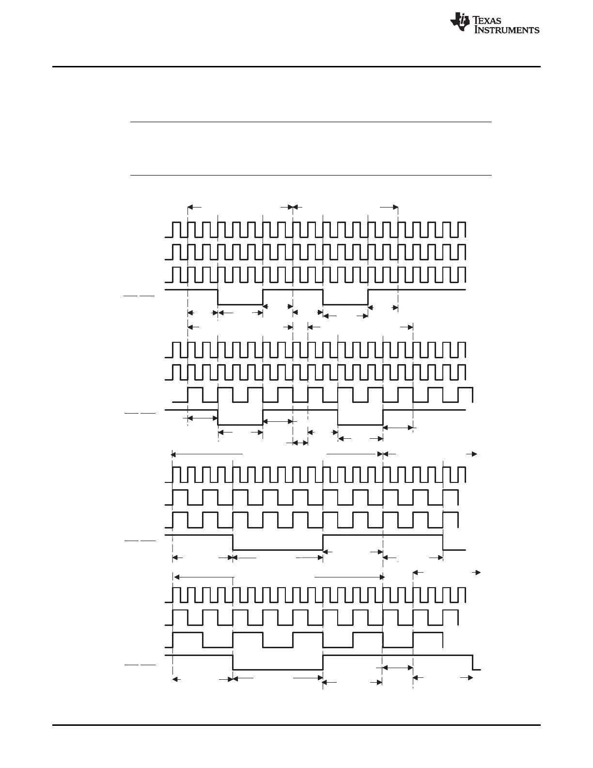
14.8 Waveforms
Figure 14-12 shows example timing waveforms for various XTIMCLK and XCLKOUT modes assuming
X2TIMING = 0 and Lead = 2, Active = 2 and Trail = 2.
NOTE: The diagrams included in this document are conceptual, cycle-by-cycle representations of
the XINTF behavior. They do not take into account any buffer delays and additional setup
times that will be found on a physical device. For more exact device-specific timing
information for the XINTF, see the data sheet electrical timing specifications for that device.
Figure 14-12. XTIMCLK and XCLKOUT Mode Waveforms
A X2TIMING = 0, XRDLEAD/XWRLEAD = 2, XRDACTIVE/XWRACTIVE = 2, XRDTRAIL/XWRTRAIL = 2
B Alignment cycle. Necessary to make sure all bus cycles start on rising edge of XCLKOUT.
 Loading...