Reset InitBoot
SelectBootMode
Call ADC_cal
Selectjump
toOTP
ExitBoot
Jumpto
0x380400
Execute
preprogrammed
OTP code
Reset InitBoot
SelectBootMode
CallADC_cal
Selectjump
toM0SARAM
ExitBoot
Jumpto
0x000000
Execution
continues
Reset InitBoot
SelectBootMode
CallADC_cal
Selectjumptoflash
ExitBoot
Jumpto
0x33FFF6
User
programmed
branchto
desired
location
www.ti.com
Bootloader Features
177
SPRUI07–March 2020
Submit Documentation Feedback
Copyright © 2020, Texas Instruments Incorporated
Boot ROM
The following boot mode is used for debug purposes:
• Branch to check boot mode
When initially debugging a device with the password locations in flash programmed (that is, secured),
the emulator takes some time to take control of the CPU. During this time, the CPU will start running
and may execute an instruction that performs an access to a protected ECSL area. If this happens, the
ECSL will trip and cause the emulator connection to be cut. Two solutions to this problem exist:
– The first is to use the Wait-In-Reset emulation mode, which will hold the device in reset until the
emulator takes control. The emulator must support this mode for this option.
– The second option is to use the “Branch to check boot mode” boot option. This will sit in a loop and
continuously poll the boot mode select pins. The user can select this boot mode and then exit this
mode once the emulator is connected by re-mapping the PC to another address or by changing the
boot mode selection pin to the desired boot mode.
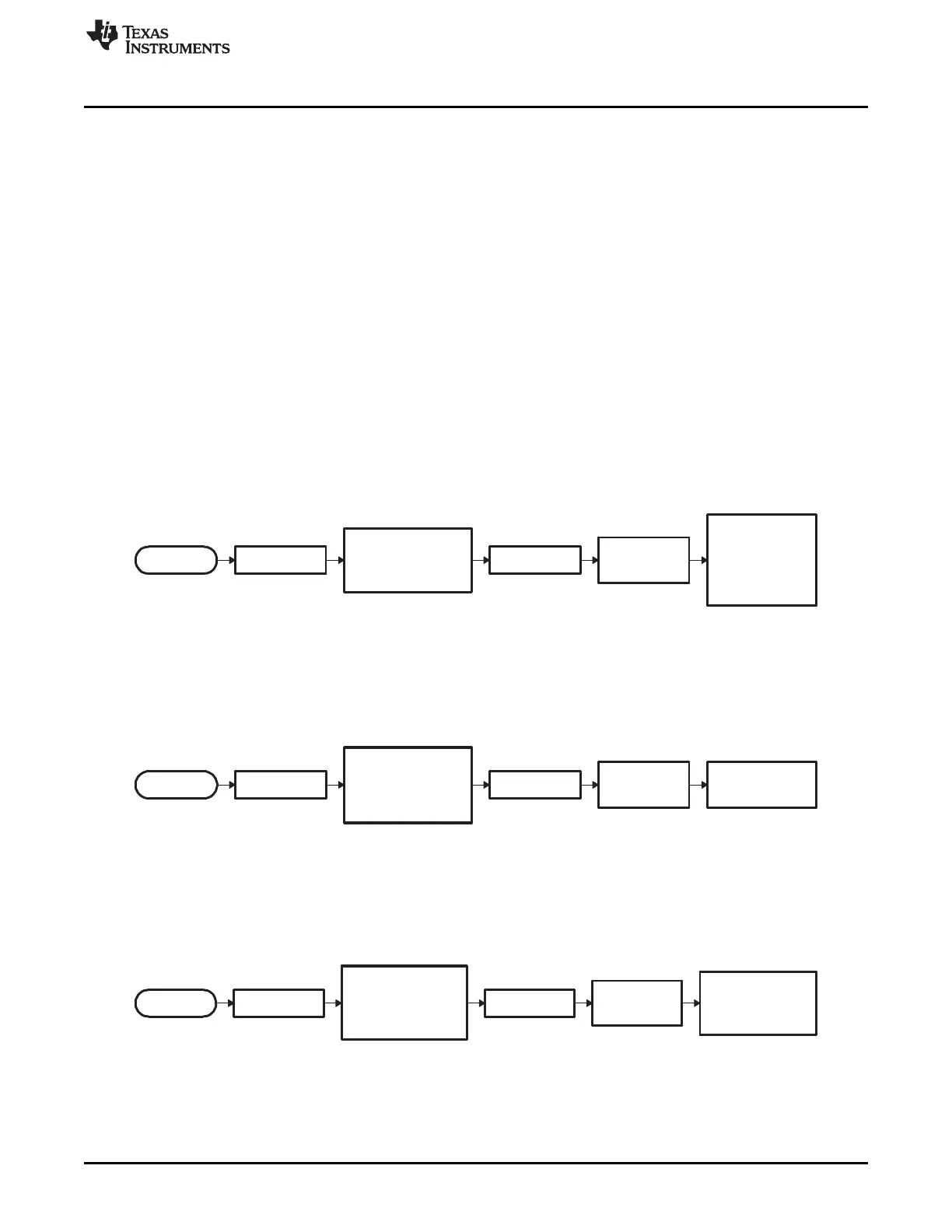
The following boot modes do not call a bootloader. Instead, they jump to a predefined location in memory:
• Jump to branch instruction in flash memory
In this mode, the boot ROM software configures the device for 28x operation and branches directly to
location 0x33 FFF6. This location is just before the 128-bit code security module (CSM) password
locations. You are required to have previously programmed a branch instruction at location 0x33 FFF6
that will redirect code execution to either a custom boot-loader or the application code.
Figure 2-6. Jump-to-Flash Flow Diagram
• Jump to M0 SARAM
In this mode, the boot ROM software configures the device for 28x operation and branches directly to
0x00 0000. This is the first address in the M0 SARAM memory block.
Figure 2-7. Flow Diagram of Jump to M0 SARAM
• Jump to OTP memory
In this mode, the boot ROM software configures the device for 28x operation and branches to 0x38
0400. This is the first address in the OTP memory block.
Figure 2-8. Flow Diagram of Jump-to-OTP Memory
 Loading...