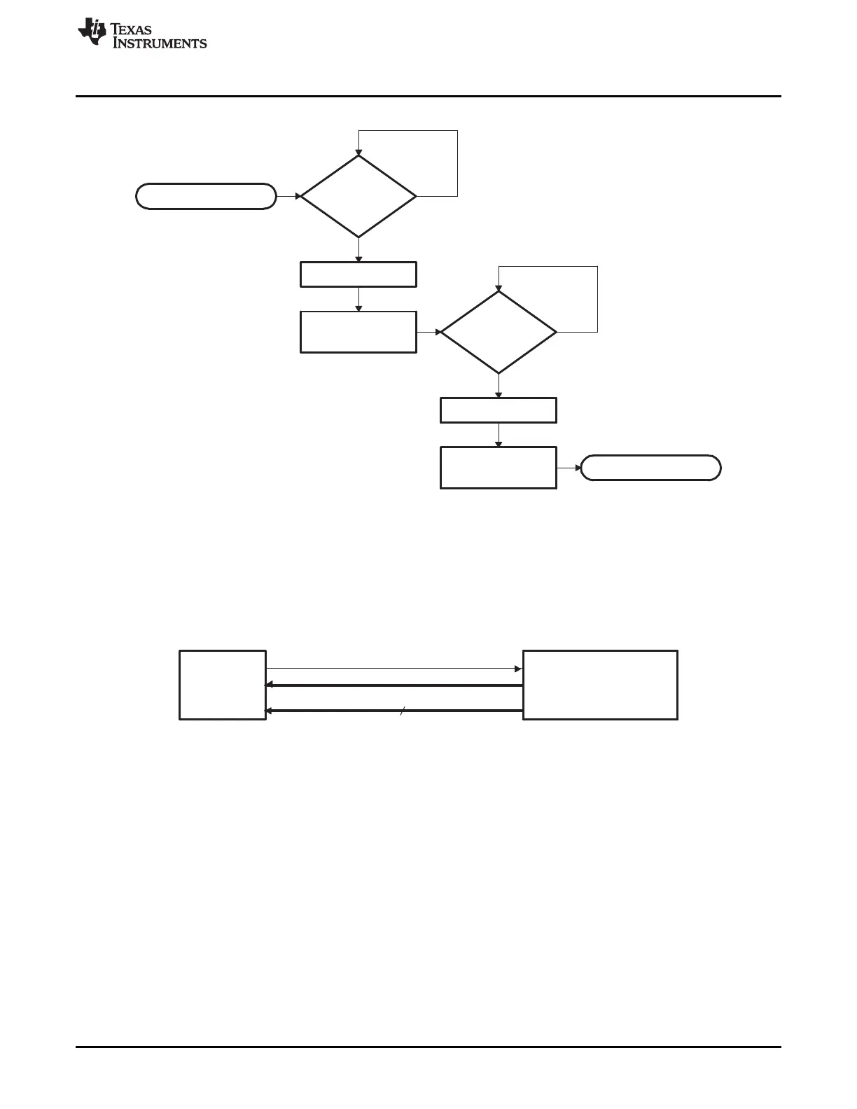
DSP
DSP control − GPIO26
Host control − GPIO27
Host
(Data and program
source)
Data GP I/O port GPIO[15:0]
16
SCIA_GetWordData
Yes
NoData
Received
?
Echoback LSB
to host
Read LSB
Data
Received
?
No
Yes
Read MSB
Echoback MSB
to host
Return MSB:LSB
www.ti.com
Bootloader Features
191
SPRUI07–March 2020
Submit Documentation Feedback
Copyright © 2020, Texas Instruments Incorporated
Boot ROM
Figure 2-17. Overview of SCI_GetWordData Function
2.2.18 Parallel_Boot Function (GPIO)
The parallel general purpose I/O (GPIO) boot mode asynchronously transfers code from GPIO0-GPIO15
to internal memory. Each value can be 16 bits or 8 bits long and follows the same data flow as outlined in
Section 2.2.10.
Figure 2-18. Overview of Parallel GPIO Bootloader Operation
The parallel GPIO loader uses following pins:
• Data on GPIO[15:0] or GPIO[7:0]
• 28x Control on GPIO26
• Host Control on GPIO27
The 28x communicates with the external host device by polling/driving the GPIO27 and GPIO26 lines. The
handshake protocol shown in Figure 2-19 must be used to successfully transfer each word via GPIO
[15:0]. This protocol is very robust and allows for a slower or faster host to communicate with the device.
If the 8-bit mode is selected, two consecutive 8-bit words are read to form a single 16-bit word. The most
significant byte (MSB) is read first followed by the least significant byte (LSB). In this case, data is read
from the lower eight lines of GPIO[7:0] ignoring the higher byte .
The 16-bit data stream is shown in Table 2-9 and the 8-bit data stream is shown in Table 2-10.
 Loading...