www.ti.com
SCI Registers
597
SPRUI07–March 2020
Submit Documentation Feedback
Copyright © 2020, Texas Instruments Incorporated
Serial Communications Interface (SCI)
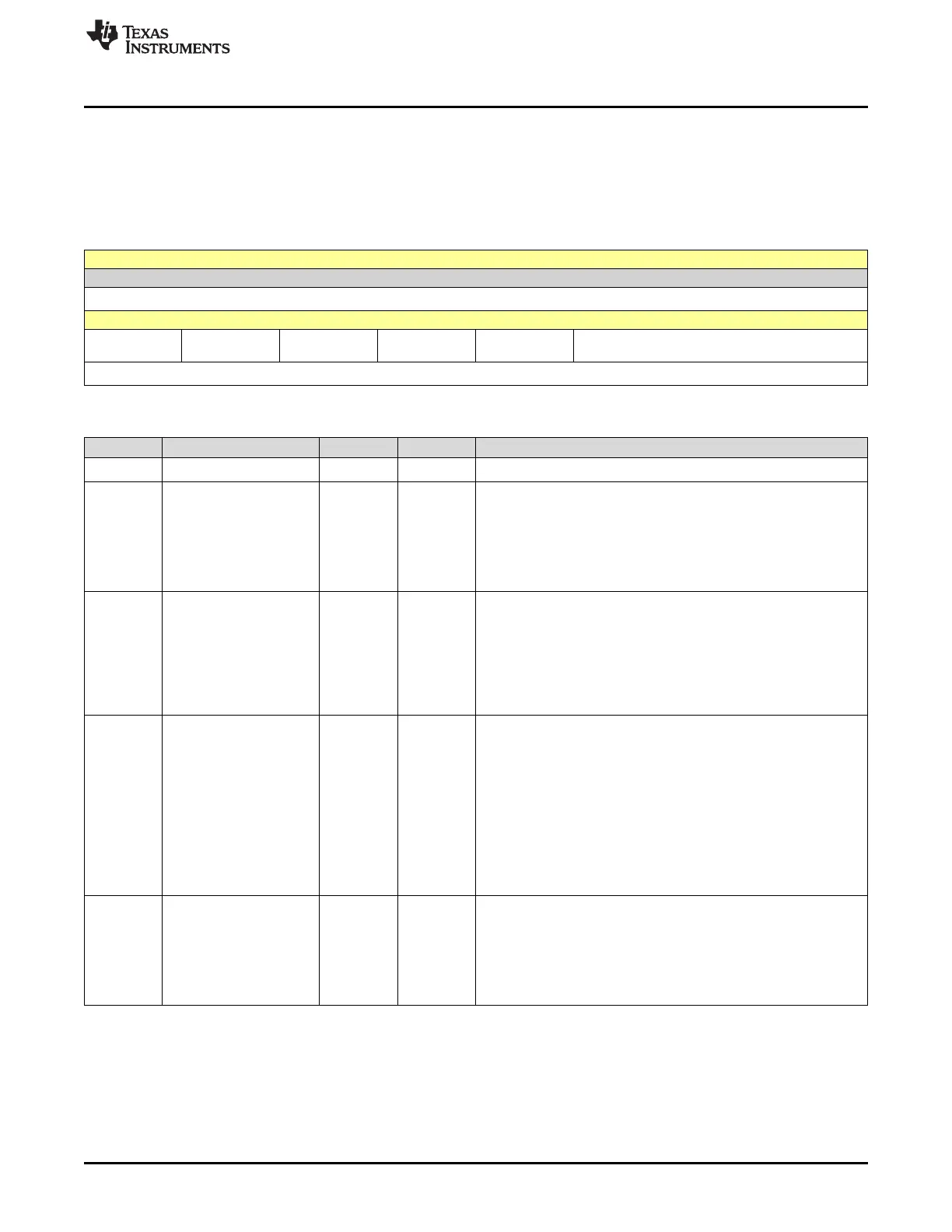
10.14.2.1 SCICCR Register (Offset = 0h) [reset = 0h]
SCICCR is shown in Figure 10-11 and described in Table 10-7.
Return to the Summary Table.
SCICCR defines the character format, protocol, and communications mode used by the SCI.
Figure 10-11. SCICCR Register
15 14 13 12 11 10 9 8
RESERVED
R-0h
7 6 5 4 3 2 1 0
STOPBITS PARITY PARITYENA LOOPBKENA ADDRIDLE_M
ODE
SCICHAR
R/W-0h R/W-0h R/W-0h R/W-0h R/W-0h R/W-0h
Table 10-7. SCICCR Register Field Descriptions
Bit Field Type Reset Description
15-8 RESERVED R 0h
Reserved
7 STOPBITS R/W 0h
SCI number of stop bits.
This bit specifies the number of stop bits transmitted. The receiver
checks for only one stop bit.
Reset type: SYSRSn
0h (R/W) = One stop bit
1h (R/W) = Two stop bits
6 PARITY R/W 0h
SCI parity odd/even selection.
If the PARITY ENABLE bit (SCICCR, bit 5) is set, PARITY (bit 6)
designates odd or even parity (odd or even number of bits with the
value of 1 in both transmitted and received characters).
Reset type: SYSRSn
0h (R/W) = Odd parity
1h (R/W) = Even parity
5 PARITYENA R/W 0h
SCI parity enable.
This bit enables or disables the parity function. If the SCI is in the
addressbit multiprocessor mode (set using bit 3 of this register), the
address bit is included in the parity calculation (if parity is enabled).
For characters of less than eight bits, the remaining unused bits
should be masked out of the parity calculation.
Reset type: SYSRSn
0h (R/W) = Parity disabled
no parity bit is generated during transmission or is expected during
reception
1h (R/W) = Parity is enabled
4 LOOPBKENA R/W 0h
Loop Back test mode enable.
This bit enables the Loop Back test mode where the Tx pin is
internally connected to the Rx pin.
Reset type: SYSRSn
0h (R/W) = Loop Back test mode disabled
1h (R/W) = Loop Back test mode enabled
 Loading...