Registers
www.ti.com
296
SPRUI07–March 2020
Submit Documentation Feedback
Copyright © 2020, Texas Instruments Incorporated
Enhanced Pulse Width Modulator (ePWM) Module
3.4 Registers
This section includes the register layouts and bit description for the submodules.
3.4.1 Time-Base Submodule Registers
Figure 3-61 through Figure 3-65 and Table 3-21 through Table 3-25 provide the time-base register
definitions.
Figure 3-61. Time-Base Period Register (TBPRD)
15 0
TBPRD
R/W-0
LEGEND: R/W = Read/Write; R = Read only; -n = value after reset
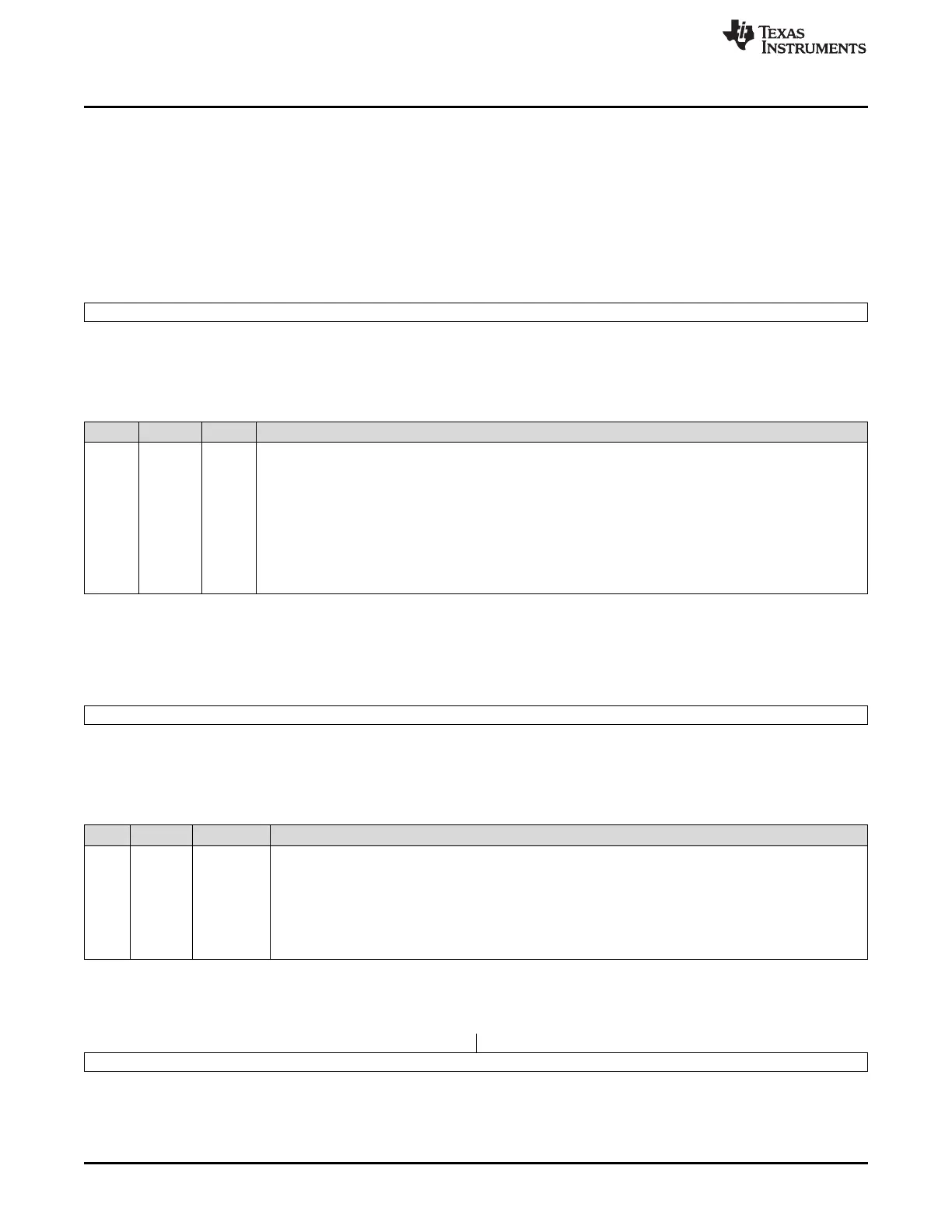
Table 3-21. Time-Base Period Register (TBPRD) Field Descriptions
Bits Name Value Description
15-0 TBPRD 0000-
FFFFh
These bits determine the period of the time-base counter. This sets the PWM frequency.
Shadowing of this register is enabled and disabled by the TBCTL[PRDLD] bit. By default this register is
shadowed.
• If TBCTL[PRDLD] = 0, then the shadow is enabled and any write or read will automatically go to the
shadow register. In this case, the active register will be loaded from the shadow register when the time-
base counter equals zero.
• If TBCTL[PRDLD] = 1, then the shadow is disabled and any write or read will go directly to the active
register, that is the register actively controlling the hardware.
• The active and shadow registers share the same memory map address.
Figure 3-62. Time-Base Phase Register (TBPHS)
15 0
TBPHS
R/W-0
LEGEND: R/W = Read/Write; R = Read only; -n = value after reset
Table 3-22. Time-Base Phase Register (TBPHS) Field Descriptions
Bits Name Value Description
15-0 TBPHS 0000-FFFF These bits set time-base counter phase of the selected ePWM relative to the time-base that is supplying
the synchronization input signal.
• If TBCTL[PHSEN] = 0, then the synchronization event is ignored and the time-base counter is not
loaded with the phase.
• If TBCTL[PHSEN] = 1, then the time-base counter (TBCTR) will be loaded with the phase (TBPHS)
when a synchronization event occurs. The synchronization event can be initiated by the input
synchronization signal (EPWMxSYNCI) or by a software forced synchronization.
Figure 3-63. Time-Base Counter Register (TBCTR)
15 0
TBCTR
R/W-0
LEGEND: R/W = Read/Write; R = Read only; -n = value after reset
 Loading...