Action
qualifier
(AQ)
Time-base (TB)
Dead
band
(DB)
Counter compare (CC)
Trip
zone
(TZ)
Event
trigger and
interrupt
(ET)
PWM
chopper
(PC)
TZ1 to TZ6
TBPRD shadow (16)
TBPRD active (16)
CTR = PRD
CTR = ZERO
CTR = CMPA
CTR = CMPB
CTR_Dir
TBCTL[SWFSYNC] (software
forced sync)
TBPHS active (16)
Counter
UP/DWN
(16 bit)
TBCTR
active
(16)
Sync
in/out
select
MUX
S0
S1
CMPA active (16)
CMPA shadow (16)
CMPB active (16)
CMPB shadow (16)
EPWMxA
EPWMxB
EPWMxSOCB
EPWMxSOCA
EPWMxINT
EPWMxSYNCI
EPWMxSYNCO
TBCTL[SWFSYNC]
CTR_PRD
TBCTL[PHSEN]
CTR_Dir
CTR = ZERO
CTR = CMPA
CTR = CMPB
16
16
16
16
16
16
Phase
control
EPWMxTZINT
CTR=ZERO
Introduction
www.ti.com
222
SPRUI07–March 2020
Submit Documentation Feedback
Copyright © 2020, Texas Instruments Incorporated
Enhanced Pulse Width Modulator (ePWM) Module
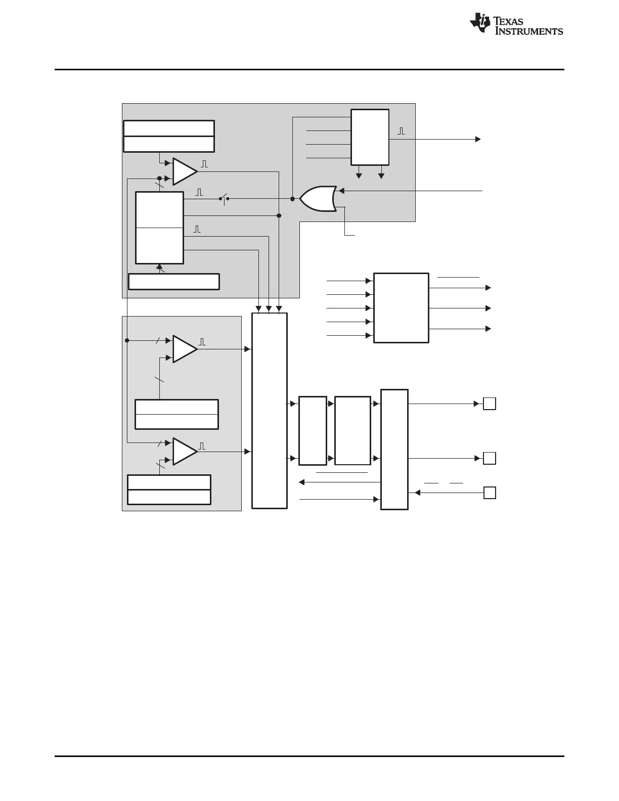
Figure 3-3. ePWM Submodules and Critical Internal Signal Interconnects
Figure 3-3 also shows the key internal submodule interconnect signals. Each submodule is described in
detail in its respective section.
3.1.2 Register Mapping
The complete ePWM module control and status register set is grouped by submodule as shown in
Table 3-1. Each register set is duplicated for each instance of the ePWM module. The start address for
each ePWM register file instance on a device is specified in the datasheet.
 Loading...