Result Registers
ePWMx SOCB
S/W
GPIO/XINT2_
ADCSOC
ePWMx SOCA
S/W
Sequencer 2Sequencer 1
SOCSOC
ADC Control Registers
Result Reg 15
Result Reg 8
Result Reg 7
Result Reg 1
Result Reg 0
module
ADC
12-Bit
Analog
MUX
ADCINA0
ADCINA7
ADCINB0
ADCINB7
System
control block
High-speed
prescaler
HSPCLK
C28x
SYSCLKOUT
S/H-A
S/H-B
ADCENCLK HALT
Features and Implementation
www.ti.com
446
SPRUI07–March 2020
Submit Documentation Feedback
Copyright © 2020, Texas Instruments Incorporated
Analog-to-Digital Converter (ADC)
7.1 Features and Implementation
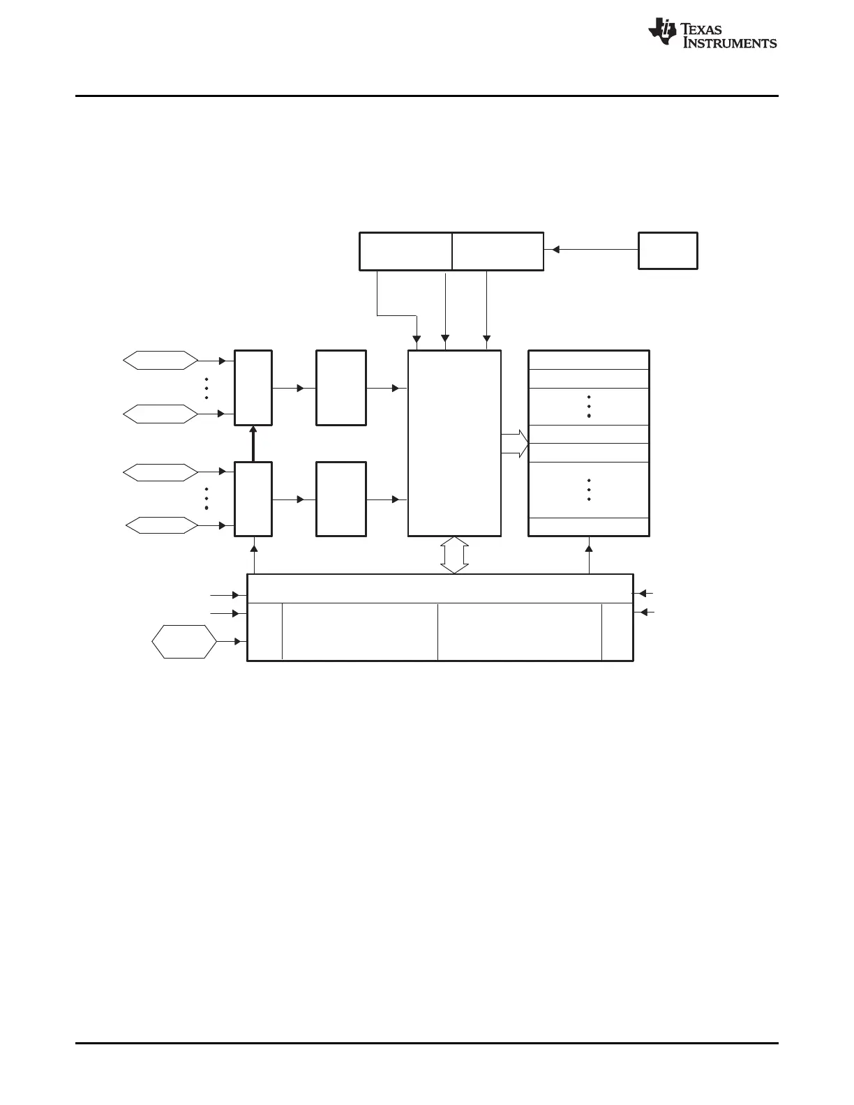
The ADC module has 16 channels, configurable as two independent 8-channel modules. The two
independent 8-channel modules can be cascaded to form a 16-channel module. Although there are
multiple input channels and two sequencers, there is only one converter in the ADC module. Figure 7-1
shows the block diagram of the ADC module.
Figure 7-1. Block Diagram of the ADC Module
 Loading...