Wait
state
Start HIGH
period
SCL from
device #1
SCL from
device #2
Bus line
SCL
I2C Module Operational Details
www.ti.com
626
SPRUI07–March 2020
Submit Documentation Feedback
Copyright © 2020, Texas Instruments Incorporated
Inter-Integrated Circuit Module (I2C)
Table 11-5. Ways to Generate a NACK Bit
I2C Module Condition NACK Bit Generation Options
Slave-receiver modes
• Allow an overrun condition (RSFULL = 1 in I2CSTR)
• Reset the module (IRS = 0 in I2CMDR)
• Set the NACKMOD bit of I2CMDR before the rising edge of the last data bit you
intend to receive
Master-receiver mode AND
Repeat mode (RM = 1 in I2CMDR)
• Generate a STOP condition (STP = 1 in I2CMDR)
• Reset the module (IRS = 0 in I2CMDR)
• Set the NACKMOD bit of I2CMDR before the rising edge of the last data bit you
intend to receive
Master-receiver mode AND
Nonrepeat mode
(RM = 0 in I2CMDR)
• If STP = 1 in I2CMDR, allow the internal data counter to count down to 0 and thus
force a STOP condition
• If STP = 0, make STP = 1 to generate a STOP condition
• Reset the module (IRS = 0 in I2CMDR). = 1 to generate a STOP condition
• Set the NACKMOD bit of I2CMDR before the rising edge of the last data bit you
intend to receive
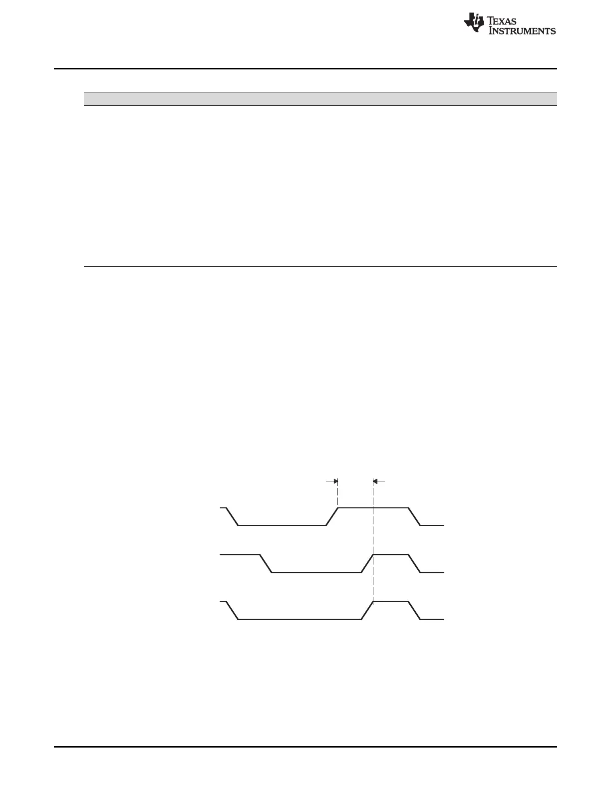
11.3.7 Clock Synchronization
Under normal conditions, only one master device generates the clock signal, SCL. During the arbitration
procedure, however, there are two or more masters and the clock must be synchronized so that the data
output can be compared. Figure 11-12 illustrates the clock synchronization. The wired-AND property of
SCL means that a device that first generates a low period on SCL overrules the other devices. At this
high-to-low transition, the clock generators of the other devices are forced to start their own low period.
The SCL is held low by the device with the longest low period. The other devices that finish their low
periods must wait for SCL to be released, before starting their high periods. A synchronized signal on SCL
is obtained, where the slowest device determines the length of the low period and the fastest device
determines the length of the high period.
If a device pulls down the clock line for a longer time, the result is that all clock generators must enter the
wait state. In this way, a slave slows down a fast master and the slow device creates enough time to store
a received byte or to prepare a byte to be transmitted.
Figure 11-12. Synchronization of Two I2C Clock Generators During Arbitration
11.3.8 Arbitration
If two or more master-transmitters attempt to start a transmission on the same bus at approximately the
same time, an arbitration procedure is invoked. The arbitration procedure uses the data presented on the
serial data bus (SDA) by the competing transmitters. Figure 11-13 illustrates the arbitration procedure
between two devices. The first master-transmitter that releases the SDA line high is overruled by another
master-transmitter that drives the SDA low. The arbitration procedure gives priority to the device that
transmits the serial data stream with the lowest binary value. Should two or more devices send identical
first bytes, arbitration continues on the subsequent bytes.
 Loading...