CS
A(19:1)
A(0)
OE
WE
D(15:0)
16-bits
External
wait-state
generator
XREADY
XCLKOUT
XZCS0/6/7
XA(19:1)
XA0/XWE1
XRD
XWE0
XD(15:0)
XINTF
XINTF Configuration Overview
www.ti.com
842
SPRUI07–March 2020
Submit Documentation Feedback
Copyright © 2020, Texas Instruments Incorporated
External Interface (XINTF)
14.2.7 Zone Data Bus Width
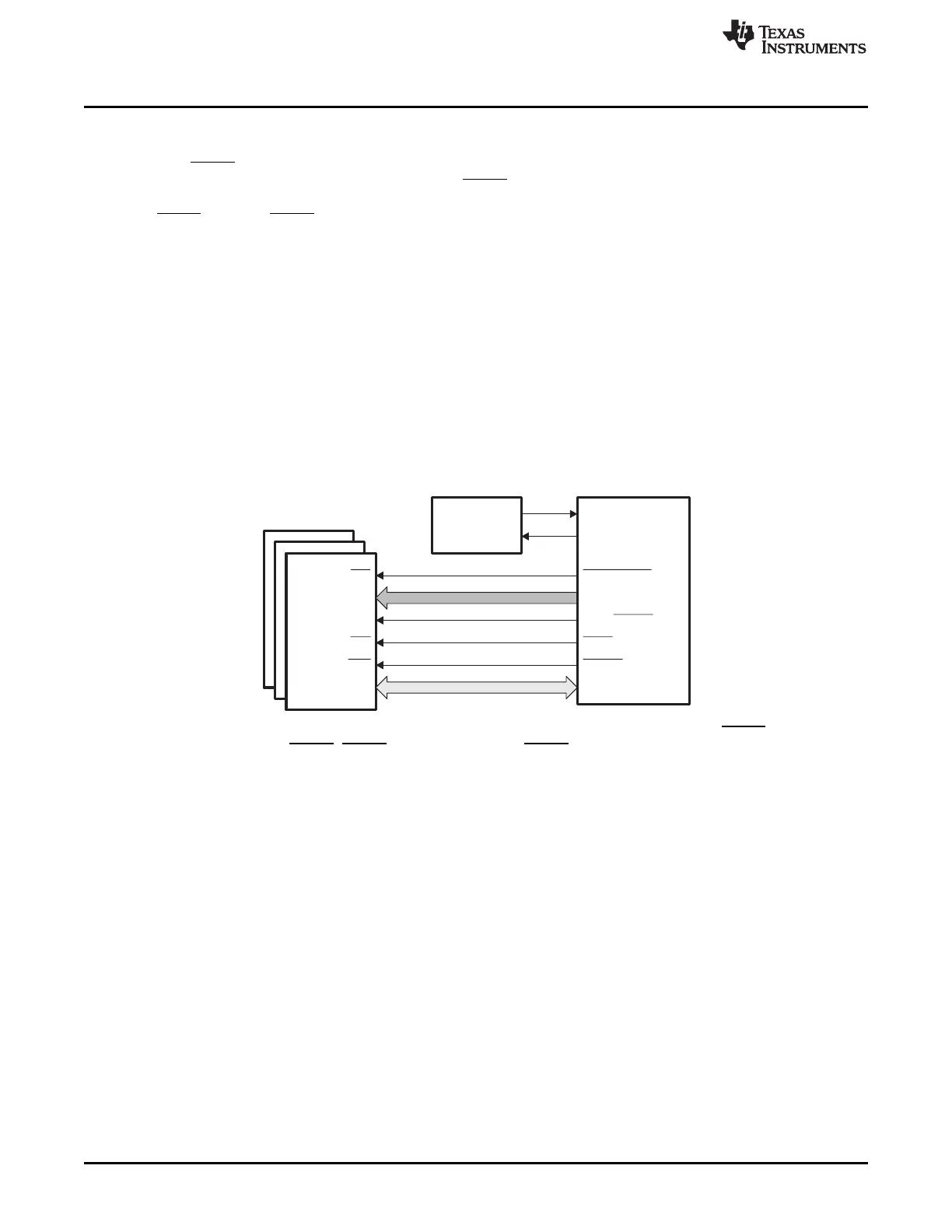
Each XINTF zone can individually be configured for a 16-bit or 32-bit wide data bus. The functionality of
the XA0/XWE1 signal changes depending on the configuration. When an XINTF zone is configured for 16-
bit mode (XTIMINGx[XSIZE] = 3), then the XA0/XWE1 signal takes on the role of least-significant address
line (XA0). In this case, a typical XINTF bus connection looks as shown in Figure 14-4. The behavior of
the XWE0 and XA0/XWE1 signals is summarized in Table 14-1 and Table 14-2.
If the width of the three zones (configured by XTIMINGx[XSIZE]) are different from each other, and there
is a possibility for back-to-back accesses between two zones of different widths, then at least one delay
cycle between the zone accesses should be added using the XBANK configuration discussed in
Section 14.5. For instance, given the zones are configured as follows:
• Zone 0 configured for 16-bit mode (XTIMING0[XSIZE] = 3)
• Zone 6 configured for 32-bit mode (XTIMING6[XSIZE] = 1)
• Zone 7 configured for 32-bit mode (XTIMING7[XSIZE] = 1)
If there is a possibility for back-to-back accesses between Zone 0 and Zone 6 or Zone 0 and Zone 7, then
at least one bank switching delay cycle should be added to Zone 0 (i.e. XBANK[BANK] = 0 and
XBANK[BCYC] = 1). See Section 14.5 for configuring XBANK cycles.
Figure 14-4. Typical 16-bit Data Bus XINTF Connections
When an XINTF zone is configured for 32-bit mode (XTIMINGx[XSIZE] = 1), the XA0/XWE1 signal is the
active low write strobe XWE1. XWE1 is used, along with XWE0 for 32-bit bus operation as shown in
Figure 14-5.
 Loading...