VCOCLK
counter
(13bits)
Clear ResClear
OSCCLK
Clear
(7bits)
counter
Res Clear
OvfClk
XRS
PLL
Clk Ovf
Off
Clear
OSCCLK
Clock
switch
logic
VCOCLK
C28x
CPU
Missing
clock
reset
PLLCLK
/1,
/2
or
/4
PLLSTS
reg
PLLCR
reg
C28x
CPU
www.ti.com
Clocking and System Control
67
SPRUI07–March 2020
Submit Documentation Feedback
Copyright © 2020, Texas Instruments Incorporated
System Control and Interrupts
(1)
PLLSTS[DIVSEL] must be 0 before writing to the PLLCR and should be changed only after PLLSTS[PLLLOCKS] = 1. See Figure 1-22.
Table 1-20. Possible PLL Configuration Modes
PLL Mode Remarks PLLSTS[DIVSEL]
(1)
SYSCLKOUT
PLL Off Invoked by the user setting the PLLOFF bit in the PLLSTS register. The PLL
block is disabled in this mode. This can be useful to reduce system noise and
for low power operation. The PLLCR register must first be set to 0x0000 (PLL
Bypass) before entering this mode. The CPU clock (CLKIN) is derived
directly from the input clock on either X1/X2, X1 or XCLKIN.
0, 1
2
3
OSCCLK/4
OSCCLK/2
OSCCLK/1
PLL Bypass PLL Bypass is the default PLL configuration upon power-up or after an
external reset (XRS). This mode is selected when the PLLCR register is set
to 0x0000 or while the PLL locks to a new frequency after the PLLCR register
has been modified. In this mode, the PLL itself is bypassed but the PLL is not
turned off.
0, 1
2
3
OSCCLK/4
OSCCLK/2
OSCCLK/1
PLL Enabled Achieved by writing a non-zero value n into the PLLCR register. Upon writing
to the PLLCR, the device will switch to PLL Bypass mode until the PLL locks.
0, 1
2
OSCCLK*n/4
OSCCLK*n/2
1.3.2.2 Main Oscillator Fail Detection
Due to vibrations, it is possible for the external clock source to the DSP to become detached and fail to
clock the device. When the PLL is not disabled, the main oscillator fail logic allows the device to detect
this condition and default to a known state as described in this section.
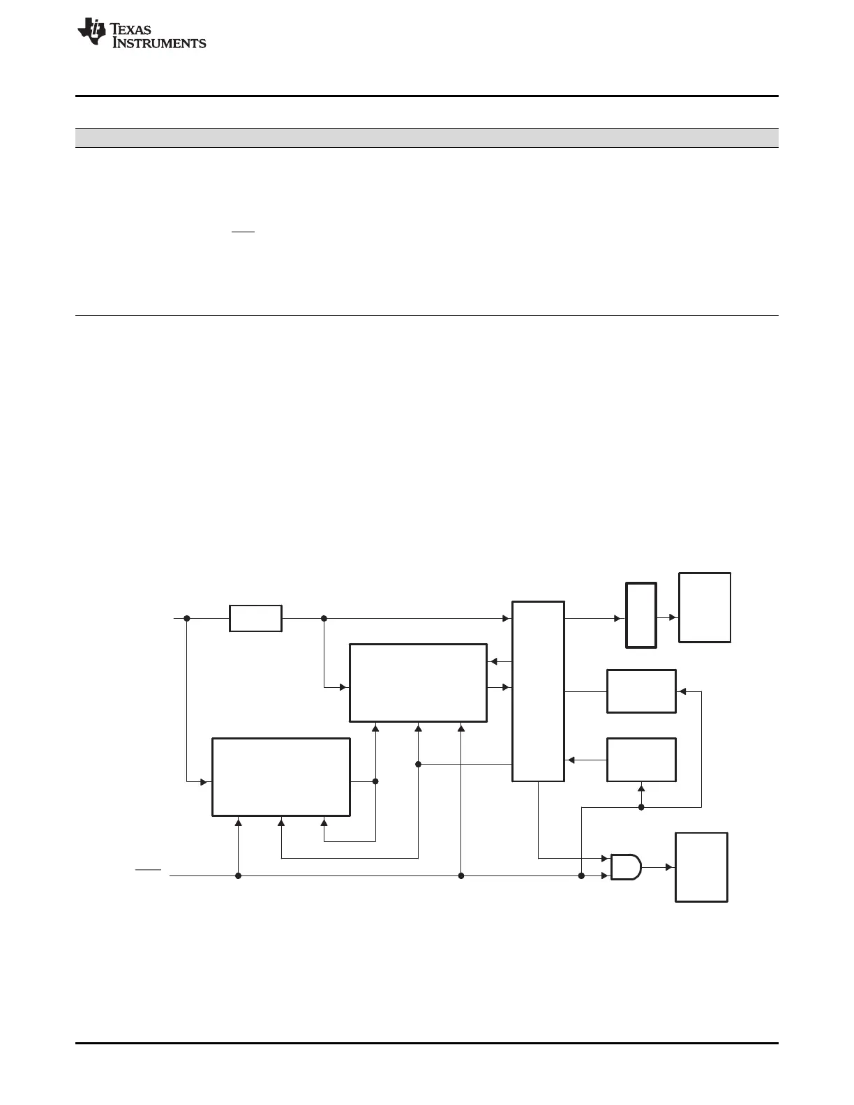
Two counters are used to monitor the presence of the OSCCLK signal as shown in Figure 1-20. The first
counter is incremented by the OSCCLK signal itself either from the X1/X2 or XCLKIN input. When the PLL
is not turned off, the second counter is incremented by the VCOCLK coming out of the PLL block. These
counters are configured such that when the 7-bit OSCCLK counter overflows, it clears the 13-bit VCOCLK
counter. In normal operating mode, as long as OSCCLK is present, the VCOCLK counter will never
overflow.
Figure 1-20. Oscillator Fail-Detection Logic Diagram
If the OSCCLK input signal is missing, then the PLL will output a default "limp mode" frequency and the
VCOCLK counter will continue to increment. Since the OSCCLK signal is missing, the OSCCLK counter
will not increment and, therefore, the VCOCLK counter is not periodically cleared. Eventually, the
VCOCLK counter overflows and, if required, the device switches the CLKIN input to the CPU to the limp
mode output frequency of the PLL.
 Loading...