Start transfer
No
More
data
?
DSP ready
(GPIO26=0)
?
Yes
Load GPIO[15:0] with data
Signal that data
is ready
(GPIO27=0)
DSP ack
(GPIO26=1)
?
No
Yes
Acknowledge DSP
(GPIO27=1)
Yes
No
End transfer
Bootloader Features
www.ti.com
194
SPRUI07–March 2020
Submit Documentation Feedback
Copyright © 2020, Texas Instruments Incorporated
Boot ROM
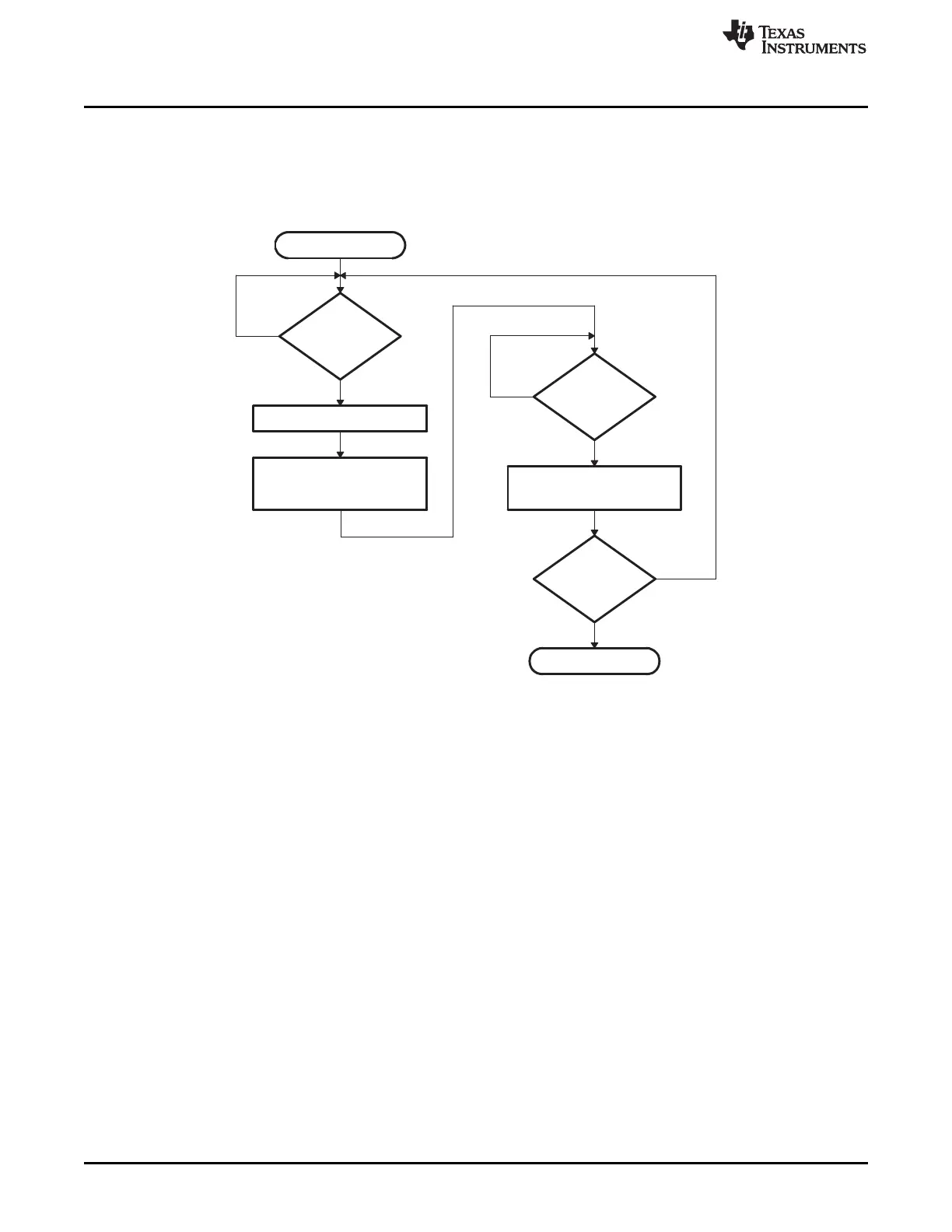
Figure 2-21 shows the transfer flow from the host side. The operating speed of the CPU and host are not
critical in this mode as the host will wait for the 28x device, and the 28x device will in turn wait for the host.
In this manner the protocol will work with both a host running faster and a host running slower than the
28x device.
Figure 2-21. Parallel GPIO Mode - Host Transfer Flow
Figure 2-22 and Figure 2-23 shows the flow used to read a single word of data from the parallel port. The
loader uses the method shown in Figure 2-11 to read the key value and to determine if the incoming data
stream width is 8-bit or 16-bit. A different GetWordData function is used by the parallel loader depending
on the data size of the incoming data stream.
• 16-bit data stream
For an 16-bit data stream, the function Parallel_GetWordData16bit is used. This function reads all 16-
bits at a time. The flow of this function is shown in Figure 2-22.
• 8-bit data stream
The 8-bit routine, shown in Figure 2-23, discards the upper 8 bits of the first read from the port and
treats the lower 8 bits as the least significant byte (LSB) of the word to be fetched. The routine will then
perform a second read to fetch the most significant byte (MSB). It then combines the MSB and LSB
into a single 16-bit value to be passed back to the calling routine.
 Loading...