25 µs
50 µs
ePWM
counter
PWM A/B
output
I
1
, I
2
, I
3
V
1
, V
2
,V
3
I
1
, I
2
, I
3
V
1
, V
2
, V
3
ADC Interface
www.ti.com
472
SPRUI07–March 2020
Submit Documentation Feedback
Copyright © 2020, Texas Instruments Incorporated
Analog-to-Digital Converter (ADC)
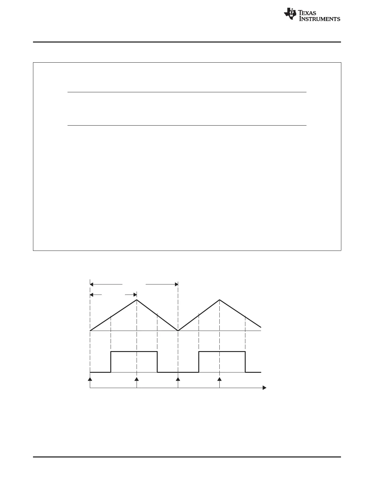
Example 7-6. Sequencer Start/Stop Operation
Requirement: To start three autoconversions (e.g., I
1
,I
2
,I
3
) off trigger 1 (underflow) and three autoconversions
(for example, V
1
,V
2
,V
3
) off trigger 2 (period). Triggers 1 and 2 are separated in time by 25 µs and are provided
by an ePWM. See Figure 7-13. Only SEQ1 is used in this case.
NOTE: Triggers 1 and 2 may be an SOC signal from ePWM, external pin, or software. The same trigger
source may occur twice to satisfy the dual-trigger requirement of this example. Care must be
taken such that multiple ePWM triggers are not lost due sequences already in progress. See
Section 7.3.1.
Here MAX_CONV1 is set to 2 and the ADC Input Channel Select Sequencing Control Registers
(ADCCHSELSEQn) are set as shown in Table 7-7.
Once reset and initialized, SEQ1 waits for a trigger. With the first trigger, three conversions with channel-
select values of: CONV00 (I
1
), CONV01 (I
2
), and CONV02 (I
3
) are performed. SEQ1 then waits at current state
for another trigger. Twenty-five microseconds later when the second trigger arrives, another three conversions
occur, with channel-select values of CONV03 (V
1
), CONV04 (V
2
), and CONV05 (V
3
).
The value of MAX_CONV1 is automatically loaded into SEQ_CNTR for both trigger cases. If a different
number of conversions are required at the second trigger point, you must (at some appropriate time before the
second trigger) change the value of MAX_CONV1 through software, otherwise, the current (originally loaded)
value will be reused. This can be done by an ISR that changes the value of MAX_CONV1 at the appropriate
time. The interrupt operation modes are described in Section 7.3.4.
At the end of the second autoconversion session, the ADC result registers will have the values shown in
Table 7-8.
At this point, SEQ1 keeps "waiting" at the current state for another trigger. Now, the user can reset SEQ1 (by
software) to state CONV00 and repeat the same trigger1, 2 sessions.
Figure 7-13. Example of ePWM Triggers to Start the Sequencer
 Loading...