www.ti.com
ADC Registers
491
SPRUI07–March 2020
Submit Documentation Feedback
Copyright © 2020, Texas Instruments Incorporated
Analog-to-Digital Converter (ADC)
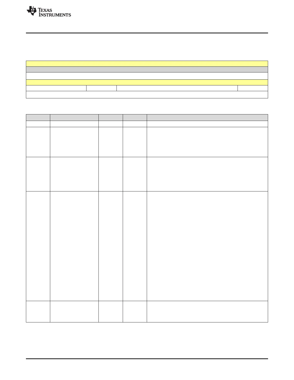
7.4.10 ADCTRL3 Register (Offset = 18h) [reset = 0h]
ADCTRL3 is shown in Figure 7-25 and described in Table 7-22.
Figure 7-25. ADCTRL3 Register
15 14 13 12 11 10 9 8
RESERVED
R-0h
7 6 5 4 3 2 1 0
ADCBGRFDN[1:0] ADCPWDN ADCCLKPS[3:0] SMODE_SEL
R/W-0h R/W-0h R/W-0h R/W-0h
Table 7-22. ADCTRL3 Register Field Descriptions
Bit Field Type Reset Description
15-8 RESERVED R 0h Reads return a zero. Writes have no effect.
7-6 ADCBGRFDN[1:0] R/W 0h ADC bandgap and reference power down. These bits control the
power up and power down of the bandgap and reference circuitry
inside the analog core. See Section 7.2.4for power-up sequence
requirements.
00b = The bandgap and reference circuitry is powered down.
11b = The bandgap and reference circuitry is powered up.
5 ADCPWDN R/W 0h ADC power down. This bit controls the power up and power down of
all the analog circuitry inside the analog core except the bandgap
and reference circuitry. See Section 7.2.4for power-up sequence
requirements.
0h = All analog circuitry inside the core except the bandgap and
reference circuitry is powered down.
1h = The analog circuitry inside the core is powered up.
4-1 ADCCLKPS[3:0] R/W 0h Core clock divider. 28x peripheral clock, HSPCLK, is divided by
2*ADCCLKPS[3-0], except when ADCCLKPS[3-0] is 0000, in which
case HSPCLK is directly passed on. The divided clock is further
divided by ADCTRL1[7]+1 to generate the core clock, ADCLK.
ADCCLKPS [3:0] Core Clock Divider ADCLK
0000b = HSPCLK/(ADCTRL1[7] + 1)
0001b = HSPCLK/[2*(ADCTRL1[7] + 1)]
0010b = HSPCLK/[4*(ADCTRL1[7] + 1)]
0011b = HSPCLK/[6*(ADCTRL1[7] + 1)]
0100b = HSPCLK/[8*(ADCTRL1[7] + 1)]
0101b = HSPCLK/[10*(ADCTRL1[7] + 1)]
0110b = HSPCLK/[12*(ADCTRL1[7] + 1)]
0111b = HSPCLK/[14*(ADCTRL1[7] + 1)]
1000b = HSPCLK/[16*(ADCTRL1[7] + 1)]
1001b = HSPCLK/[18*(ADCTRL1[7] + 1)]
1010b = HSPCLK/[20*(ADCTRL1[7] + 1)]
1011b = HSPCLK/[22*(ADCTRL1[7] + 1)]
1100b = HSPCLK/[24*(ADCTRL1[7] + 1)]
1101b = HSPCLK/[26*(ADCTRL1[7] + 1)]
1110b = HSPCLK/[28*(ADCTRL1[7] + 1)]
1111b = HSPCLK/[30*(ADCTRL1[7] + 1)]
0 SMODE_SEL R/W 0h Sampling mode select. This bit selects either sequential or
simultaneous sampling mode.
0h = Sequential sampling mode is selected.
1h = Simultaneous sampling mode is selected.
 Loading...