Operational Description of HRPWM
www.ti.com
340
SPRUI07–March 2020
Submit Documentation Feedback
Copyright © 2020, Texas Instruments Incorporated
High-Resolution Pulse Width Modulator (HRPWM)
Example 4-5. #Defines for HRPWM Header Files
//--------------------------------
// HRPWM (High Resolution PWM)
//================================
// HRCNFG
#define HR_Disable 0x0
#define HR_REP 0x1 // Rising Edge position
#define HR_FEP 0x2 // Falling Edge position
#define HR_BEP 0x3 // Both Edge position
#define HR_CMP 0x0 // CMPAHR controlled
#define HR_PHS 0x1 // TBPHSHR controlled
#define HR_CTR_ZERO 0x0 // CTR = Zero event
#define HR_CTR_PRD 0x1 // CTR = Period event
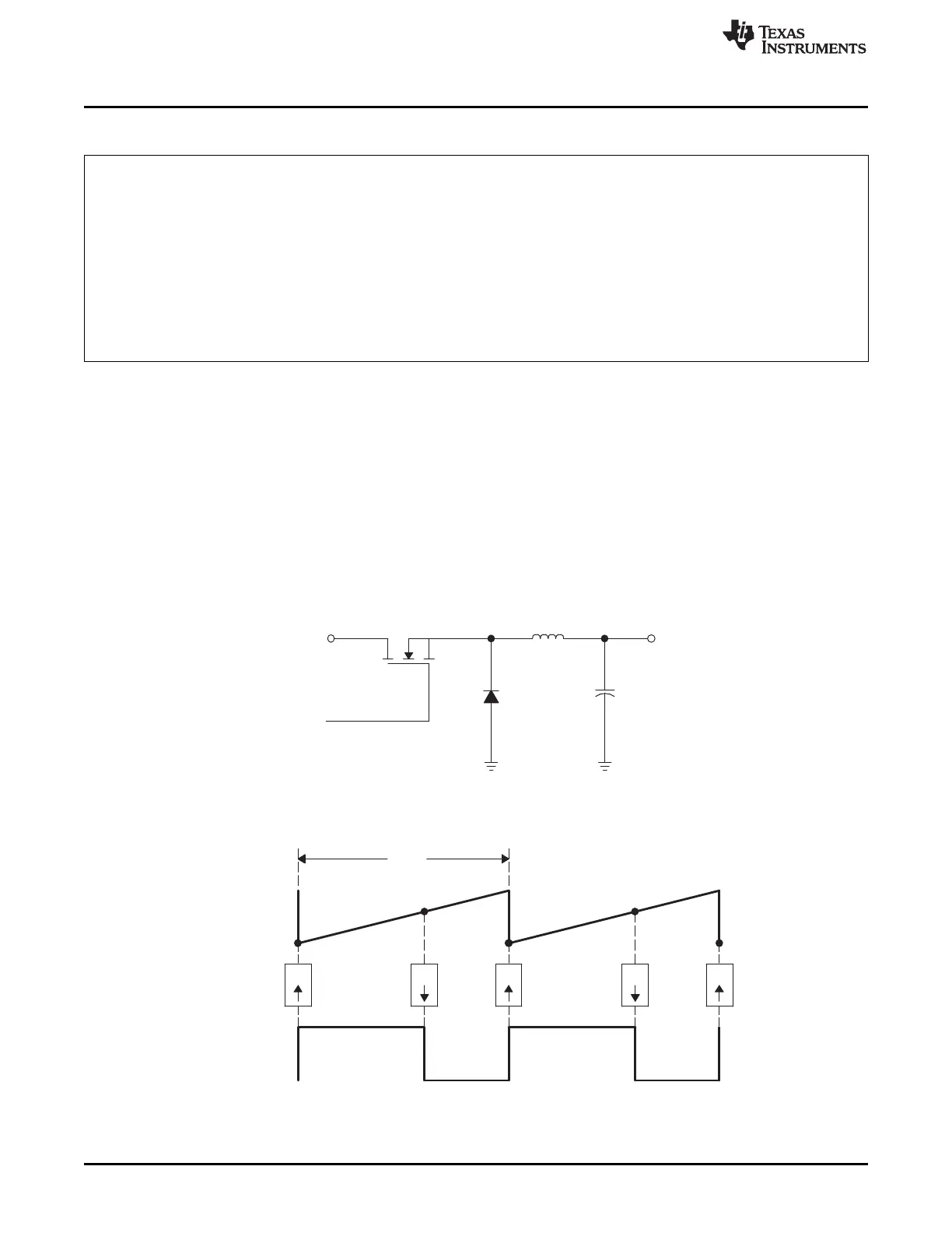
4.2.5.1 Implementing a Simple Buck Converter
In this example, the PWM requirements are:
• PWM frequency = 1 MHz (that is, TBPRD = 100 )
• PWM mode = asymmetrical, up-count
• Resolution = 12.7 bits (with a MEP step size of 150 ps)
Figure 4-8 and Figure 4-9 show the required PWM waveform. As explained previously, configuration for
the ePWM1 module is almost identical to the normal case except that the appropriate MEP options need
to be enabled/selected.
Figure 4-8. Simple Buck Controlled Converter Using a Single PWM
Figure 4-9. PWM Waveform Generated for Simple Buck Controlled Converter
 Loading...