www.ti.com
HRPWM Registers
347
SPRUI07–March 2020
Submit Documentation Feedback
Copyright © 2020, Texas Instruments Incorporated
High-Resolution Pulse Width Modulator (HRPWM)
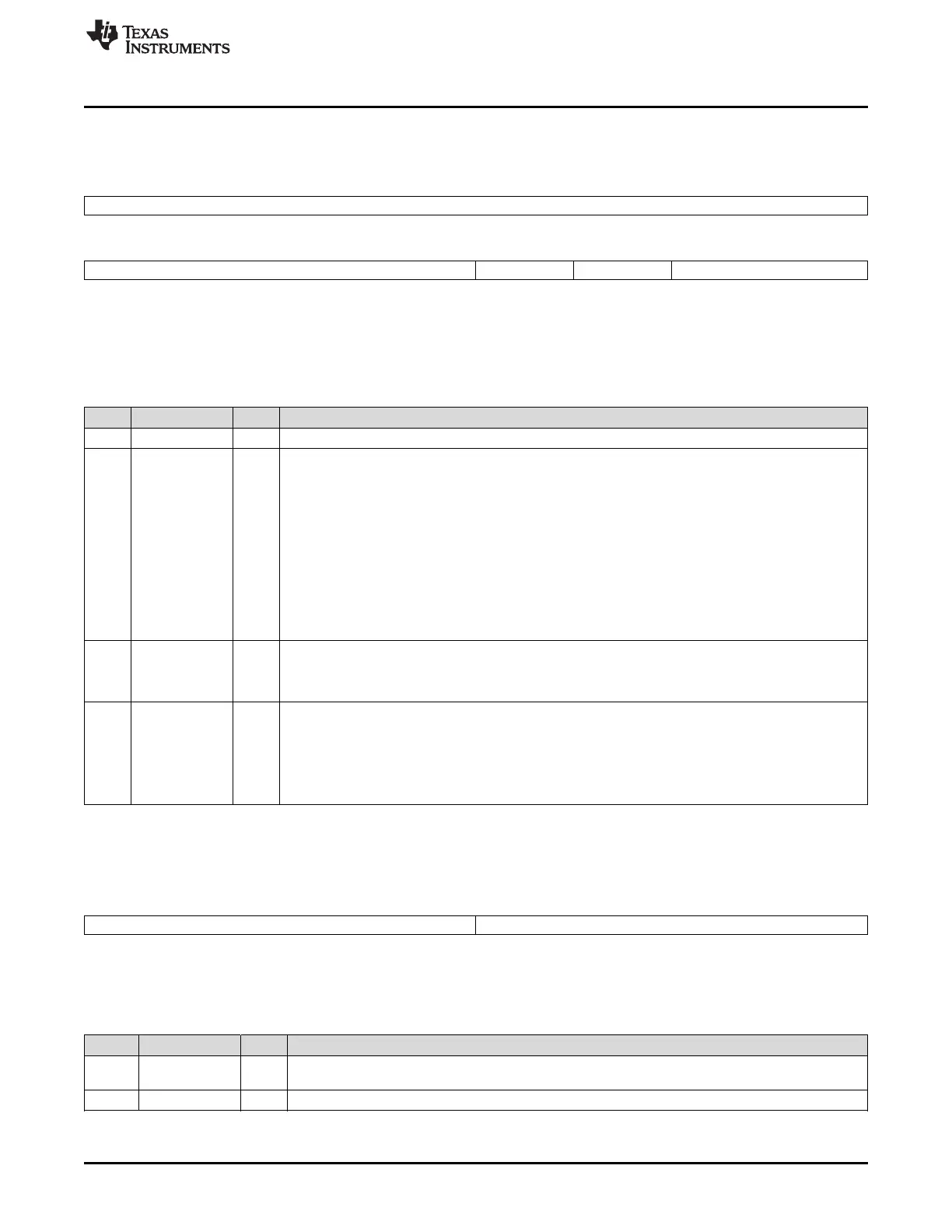
4.3.2 Registers and Field Descriptions
Figure 4-12. HRPWM Configuration Register (HRCNFG)
15 8
Reserved
R-0
7 4 3 2 1 0
Reserved HRLOAD CTLMODE EDGMODE
R-0 R/W-0 R/W-0 R/W-0
LEGEND: R/W = Read/Write; R = Read only; -n = value after reset
(1)
This register is EALLOW protected.
Table 4-9. HRPWM Configuration Register (HRCNFG) Field Descriptions
Bit Field Value Description
(1)
15-4 Reserved Reserved
3 HRLOAD Shadow mode bit: Selects the time event that loads the CMPAHR shadow value into the active register:
0 CTR = zero (counter equal zero)
1 CTR=PRD (counter equal period)
Note: Load mode selection is valid only if CTLMODE=0 has been selected (bit 2). You should select this
event to match the selection of the CMPA load mode (that is, CMPCTL[LOADMODE] bits) in the EPWM
module as follows:
00 Load on CTR = Zero: Time-base counter equal to zero (TBCTR = 0x0000)
01 Load on CTR = PRD: Time-base counter equal to period (TBCTR = TBPRD)
10 Load on either CTR = Zero or CTR = PRD (should not be used with HRPWM)
11 Freeze (no loads possible – should not be used with HRPWM)
2 CTLMODE Control Mode Bits: Selects the register (CMP or TBPHS) that controls the MEP:
0 CMPAHR(8) Register controls the edge position (that is, this is duty control mode). (default on reset)
1 TBPHSHR(8) Register controls the edge position (that is, this is phase control mode).
1-0 EDGMODE Edge Mode Bits: Selects the edge of the PWM that is controlled by the micro-edge position (MEP) logic:
00 HRPWM capability is disabled (default on reset)
01 MEP control of rising edge
10 MEP control of falling edge
11 MEP control of both edges
Figure 4-13. Counter Compare A High-Resolution Register (CMPAHR)
15 8 7 0
CMPAHR Reserved
R/W-0 R-0
LEGEND: R/W = Read/Write; R = Read only; -n = value after reset
Table 4-10. Counter Compare A High-Resolution Register (CMPAHR) Field Descriptions
Bit Field Value Description
15-8 CMPAHR Compare A High Resolution register bits for MEP step control. A minimum value of 0x0001 is needed
to enable HRPWM capabilities. Valid MEP range of operation 1-255h.
7-0 Reserved Any writes to these bit(s) must always have a value of 0.
 Loading...