www.ti.com
Registers
309
SPRUI07–March 2020
Submit Documentation Feedback
Copyright © 2020, Texas Instruments Incorporated
Enhanced Pulse Width Modulator (ePWM) Module
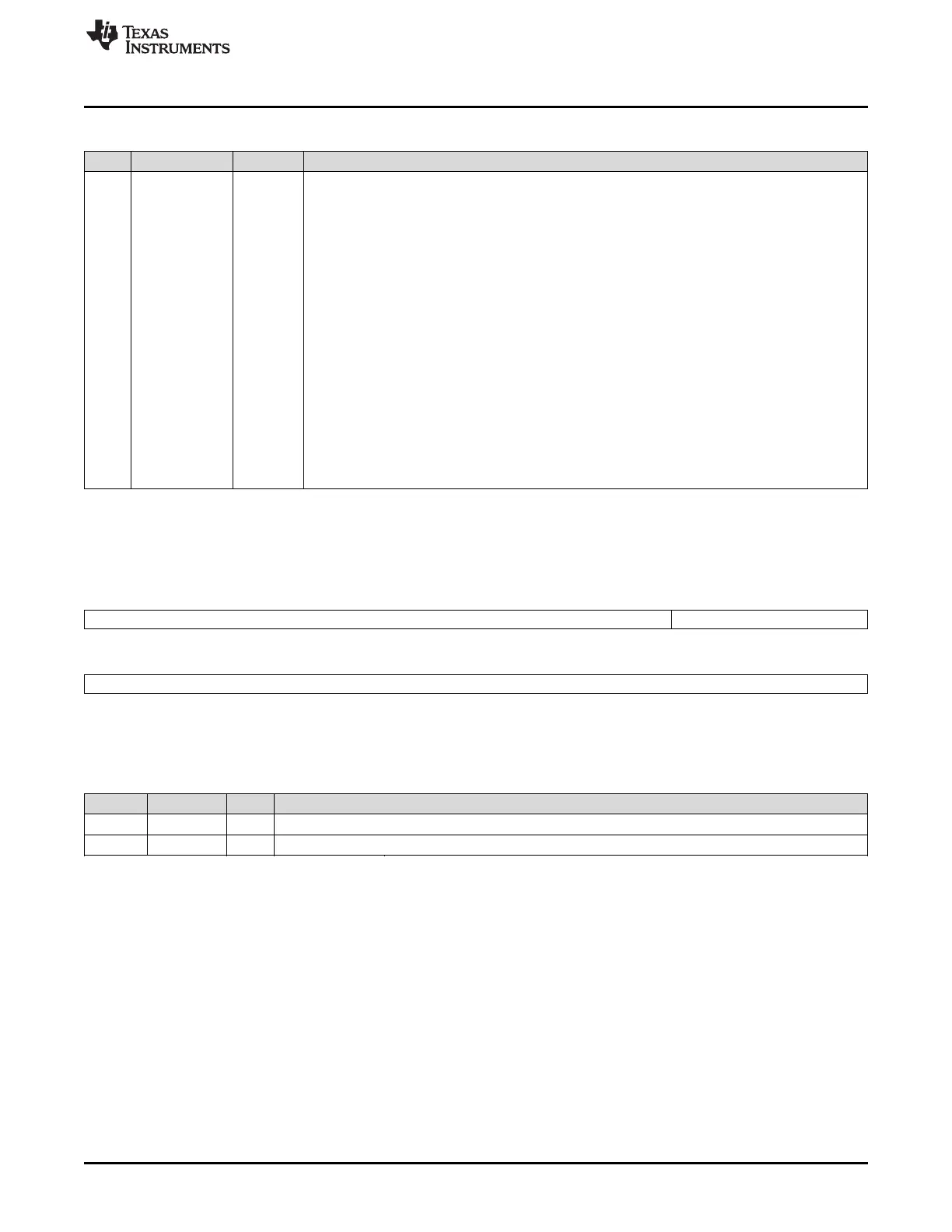
Table 3-34. Dead-Band Generator Control Register (DBCTL) Field Descriptions (continued)
Bits Name Value Description
1-0 OUT_MODE Dead-band Output Mode Control
Bit 1 controls the S1 switch and bit 0 controls the S0 switch shown in Figure 3-29.
This allows you to selectively enable or bypass the dead-band generation for the falling-edge and
rising-edge delay.
00 Dead-band generation is bypassed for both output signals. In this mode, both the EPWMxA and
EPWMxB output signals from the action-qualifier are passed directly to the PWM-chopper
submodule.
In this mode, the POLSEL and IN_MODE bits have no effect.
01 Disable rising-edge delay. The EPWMxA signal from the action-qualifier is passed straight through
to the EPWMxA input of the PWM-chopper submodule.
The falling-edge delayed signal is seen on output EPWMxB. The input signal for the delay is
determined by DBCTL[IN_MODE].
10 The rising-edge delayed signal is seen on output EPWMxA. The input signal for the delay is
determined by DBCTL[IN_MODE].
Disable falling-edge delay. The EPWMxB signal from the action-qualifier is passed straight through
to the EPWMxB input of the PWM-chopper submodule.
11 Dead-band is fully enabled for both rising-edge delay on output EPWMxA and falling-edge delay on
output EPWMxB. The input signal for the delay is determined by DBCTL[IN_MODE].
Figure 3-75. Dead-Band Generator Rising Edge Delay Register (DBRED)
15 10 9 8
Reserved DEL
R-0 R/W-0
7 0
DEL
R/W-0
LEGEND: R/W = Read/Write; R = Read only; -n = value after reset
Table 3-35. Dead-Band Generator Rising Edge Delay Register (DBRED) Field Descriptions
Bits Name Value Description
15-10 Reserved Reserved
9-0 DEL Rising Edge Delay Count. 10-bit counter.
 Loading...