4
O
=
1IO
2 ® 33J(
= 15.2G3 \ 12k3
%
O
= 1.6L( F
2
12
.5$
0.25 .5$
G= 26.2J( \ 33J(
www.ti.com
ADC Circuit
453
SPRUI07–March 2020
Submit Documentation Feedback
Copyright © 2020, Texas Instruments Incorporated
Analog-to-Digital Converter (ADC)
• n = ADC resolution (in bits)
• R
on
= ADC sampling switch resistance
• C
h
= ADC sampling capacitor
• C
p
= ADC parasitic pin capacitance for the channel
And the following parameters are dependent on the application design:
• settling error = tolerable settling error (in LSBs)
• t
recovery
= amount of time between ADC samples
• n
τ
= number of RC time constants that comprise t
recovery
• R
s
= ADC driving circuit source impedance
• C
s
= ADC driving circuit source capacitance on ADC input pin
• f
ADCCLK
= ADC clock frequency
The selection of n
τ
will determine how much the voltage on C
s
is able to recover between samples. An
insufficient amount of recovery time will introduce a droop error by way of an undercharged C
s
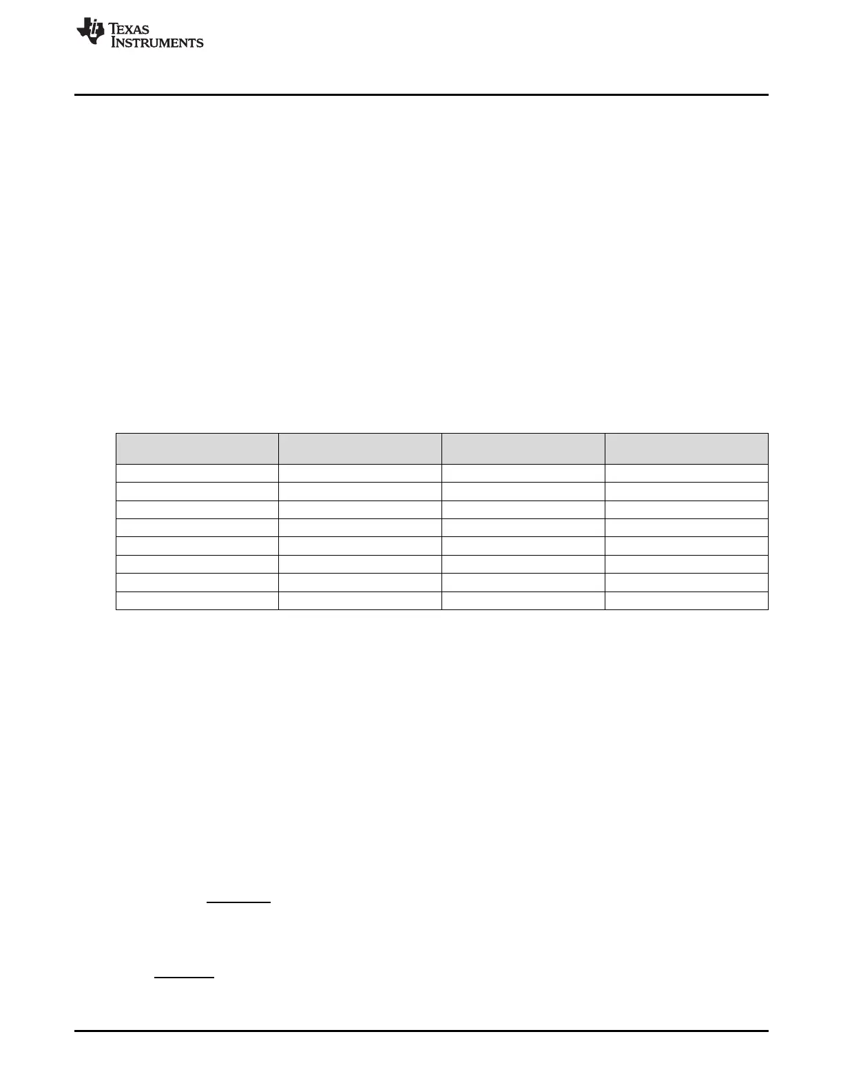
. Table 7-2
shows the relationship between n
τ
and the estimated droop error.
Table 7-2. Estimated Droop Error from n
τ
Value
n
τ
Droop Error
(% of Settling Error)
Droop Error for C
s
sized to
¼ LSB Settling Error (LSB)
Total Error (Droop Error +
¼ LSB Settling Error)
0.25 352% 0.88 LSB 1.13 LSB
0.50 154% 0.39 LSB 0.64 LSB
0.75 90% 0.23 LSB 0.48 LSB
1.00 58% 0.15 LSB 0.40 LSB
2.00 16% 0.04 LSB 0.29 LSB
3.00 5% 0.01 LSB 0.26 LSB
4.00 2% 0.01 LSB 0.26 LSB
5.00 1% 0.00 LSB 0.25 LSB
7.2.2.2.2 ACQPS Approximation Example for Low Bandwidth Signals
For example, assuming the following parameters:
• n = 12-bits
• settling error =¼ LSB
• t
recovery
= 1ms
• n
τ
= 2
• R
on
= 3400Ω
• C
h
= 1.6pF
• C
p
= 5pF
• f
ADCCLK
= 30MHz
The minimum source capacitance would be calculated and rounded up to a common value:
Then the maximum source resistance would be calculated and rounded down to a common value:
Now the time constant (τ) and multiple (k) can be calculated as:
 Loading...