EPWM1A
CA
T
PWM
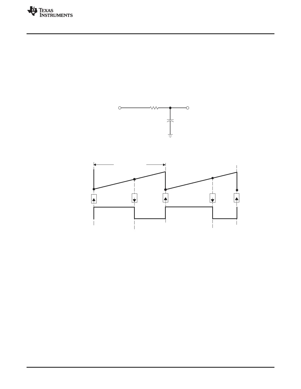
= 2.5 µs
Z
CA
ZZ
www.ti.com
Operational Description of HRPWM
343
SPRUI07–March 2020
Submit Documentation Feedback
Copyright © 2020, Texas Instruments Incorporated
High-Resolution Pulse Width Modulator (HRPWM)
4.2.5.2 Implementing a DAC function Using an R+C Reconstruction Filter
In this example, the PWM requirements are:
• PWM frequency = 400 kHz (that is, TBPRD = 250)
• PWM mode = Asymmetrical, Up-count
• Resolution = 14 bits ( MEP step size = 150 ps)
Figure 4-10 and Figure 4-11 show the DAC function and the required PWM waveform. As explained
previously, configuration for the ePWM1 module is almost identical to the normal case except that the
appropriate MEP options need to be enabled/selected.
Figure 4-10. Simple Reconstruction Filter for a PWM Based DAC
Figure 4-11. PWM Waveform Generated for the PWM DAC Function
The example code shown consists of two main parts:
• Initialization code (executed once)
• Run time code (typically executed within an ISR)
This example assumes a typical MEP_ScaleFactor and does not use the SFO library.
 Loading...