Peripheral Interrupt Expansion (PIE)
www.ti.com
162
SPRUI07–March 2020
Submit Documentation Feedback
Copyright © 2020, Texas Instruments Incorporated
System Control and Interrupts
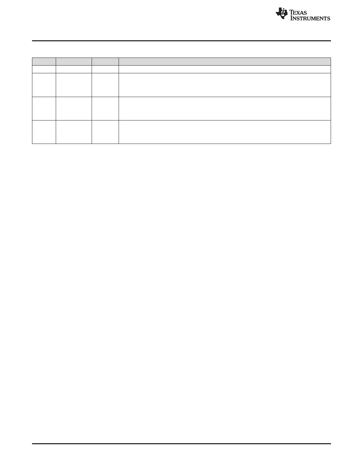
Table 1-120. Debug Interrupt Enable Register (DBGIER) — CPU Register Field Descriptions (continued)
Bits Field Value Description
1 Level INT4 is enabled
2 INT3 Interrupt 3 enable.INT3 enables or disables CPU interrupt level INT3.
0 Level INT3 is disabled
1 Level INT3 is enabled
1 INT2 Interrupt 2 enable.INT2 enables or disables CPU interrupt level INT2.
0 Level INT2 is disabled
1 Level INT2 is enabled
0 INT1 Interrupt 1 enable.INT1 enables or disables CPU interrupt level INT1.
0 Level INT1 is disabled
1 Level INT1 is enabled
 Loading...